Co-simulation with JMAG FEA Model
Download JMAG port information xml
Introduction
The JMAG direct coupling block in the SIMBA Model Library runs co-simulation with a JMAG finite element analysis (FEA) model. When using this block, the FEA will be performed while exchanging physical values, such as voltage, current, and torque, with power electronics circuits in SIMBA.
In this example, the setup for running this block will be demonstrated using a motor drive inverter system as an example.
JMAG is an FEA software developed by JSOL Corporation for the design and simulation of electromagnetic components, including motors and transformers. Both JMAG and JMAG-Designer are registered trademarks of JSOL Corporation. (https://www.jmag-international.com/)
Prerequisite
To use the JMAG direct coupling block, you must have JMAG-Designer installed on your computer. For the JMAG operation and licensing information, contact a JMAG distributor in your region listed in this link (https://www.jmag-international.com/aboutus/members/)
Info
JMAG requires an environment variable named "InsDir" to be defined on your machine. This variable must be set to the path of the JMAG installation folder. For instance, if you have installed JMAG v24.1 in the default directory, you should set the variable as follows: InsDir=C:\Program Files\JMAG-Designer24.1
Motor drive inverter model
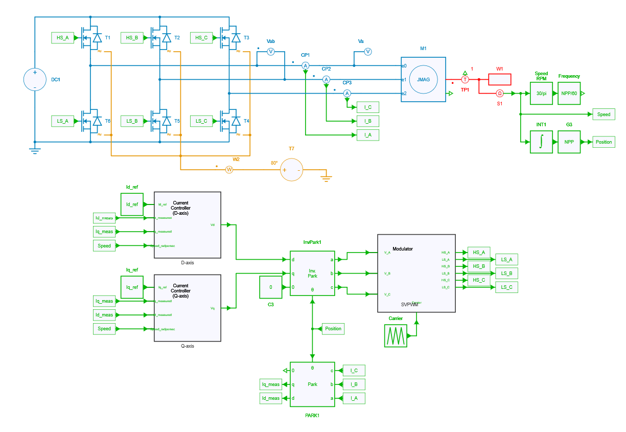
Inverter and control
The motor drive inverter model consists of a 3-phase 2-level voltage source inverter (VSI) and the current vector control with PI current regulator. The details of control can be found in another example.
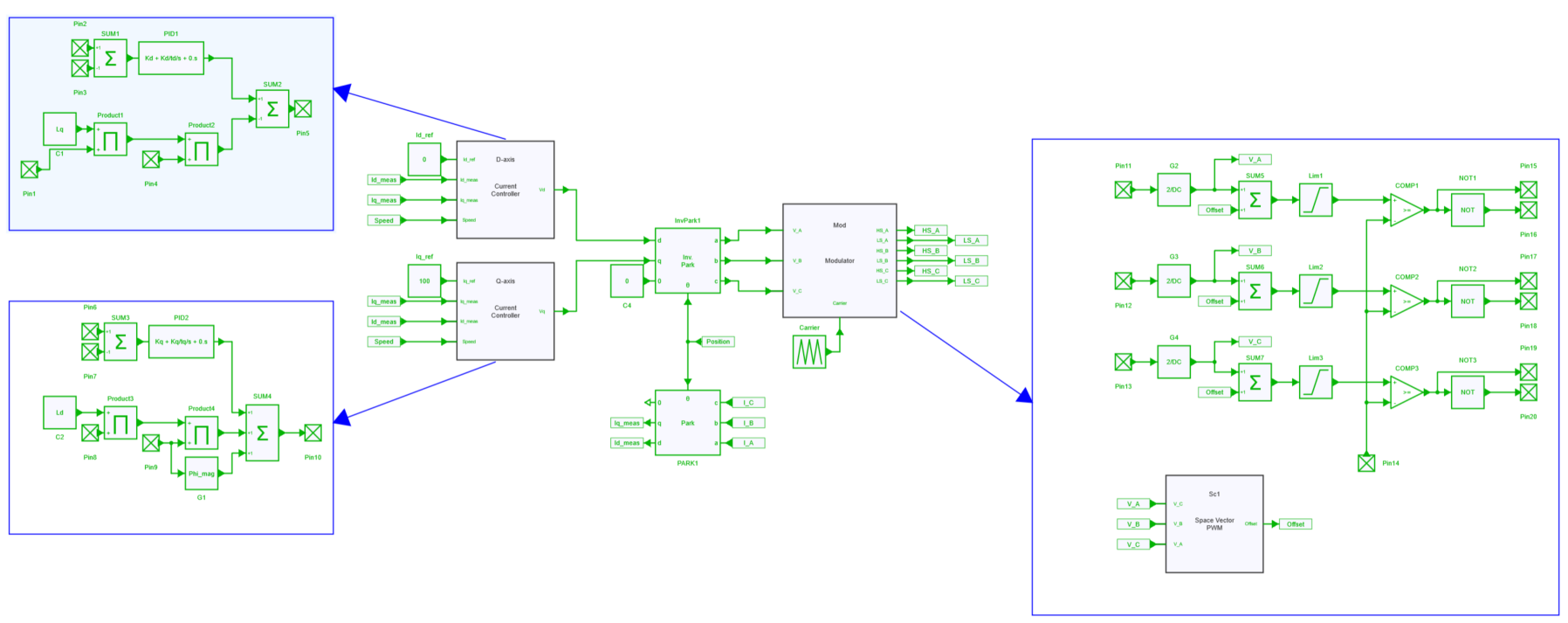
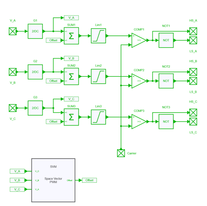
Carrier-based space vector modulation is employed as the modulation technique in this example.
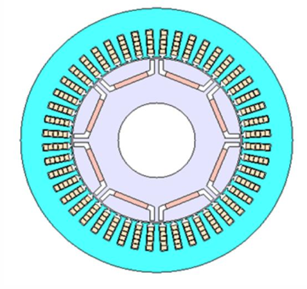
Motor
In this example, an 8-pole 48-slot PMSM model with specifications listed in table below will be used.
| Motor specifications | |
|---|---|
| Motor Type | PMSM |
| Max. Power | 80 kW |
| DC Voltage | 600 V |
| Max. Current | 250 A |
| Number of Poles | 8 |
| Number of Slots | 48 |
| Number of Phases | 3 |
| Magnet | NdFeB, Br=1.2T |
| core material | 35JA300 |
Info
For detailed specifications of the motor, refer to JSOL website. The input .jcf file for this co-simulation example was created based on the jproj file distributed on this JSOL website.
Settings
Co-simulation settings in JMAG
Co-simulation settings in SIMBA
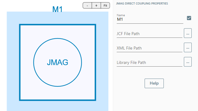
To use the JMAG direct coupling block, file paths for JMAG input files prepared following the steps in the above video need to be specified in the block properties. Details of the JMAG direct coupling block properties can be found in the table below.
| Parameters | |
|---|---|
| JCF File Path | Path to the JMAG input file (String) |
| Xml File Path | Path to the port XML File (String) |
| Library File Path | Path to the JMAG library, jbdll.dll. (String) |
Results
The waveforms from this co-simulation example is shown as below.
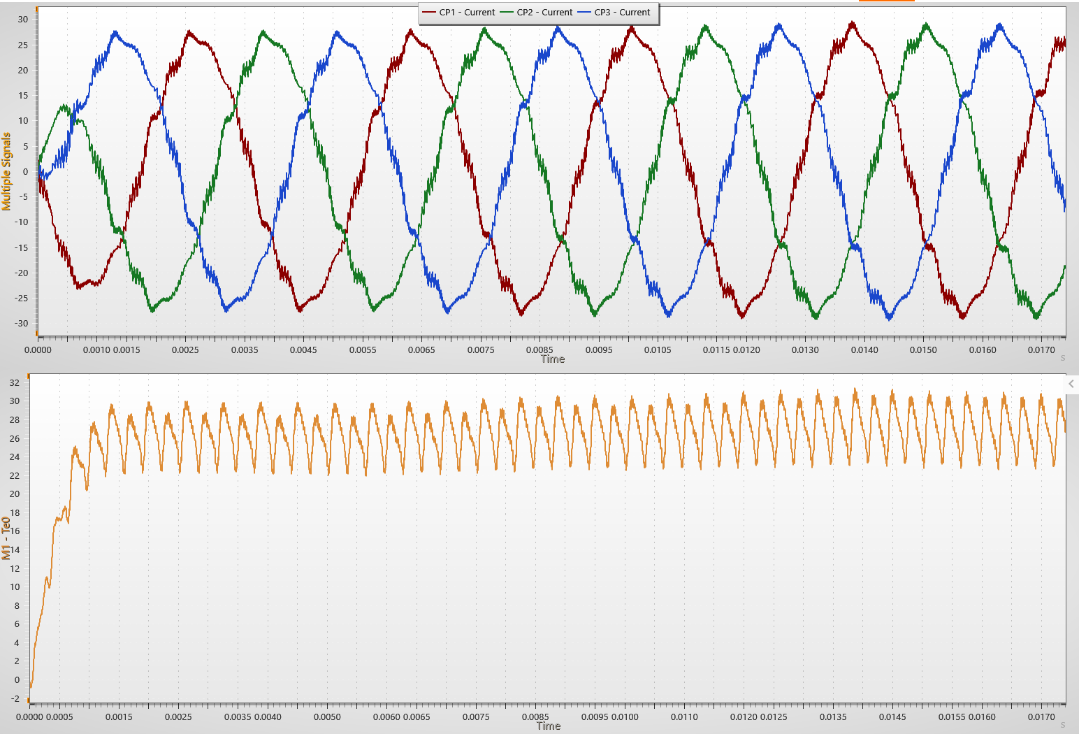
The top plot shows the three-phase currents. These currents are nearly sinusoidal but include high-frequency ripple and harmonic distortion caused by PWM switching. Unlike ideal models, these waveforms reflect the magnetic saturation and nonlinearities captured by FEA.
The bottom plot shows the electromagnetic torque waveform from the FEA model. It shows that the ripple comes from slotting effects, current ripple, and magnetic cross-coupling. This is possible because SIMBA receives real-time torque updates from JMAG's FEA solver. As a result, a highly accurate picture of machine performance can be obtained under inverter operation.
The FEA results calculated during the SIMBA-JMAG co-simulation can be opened in JMAG-Designer as shown below.
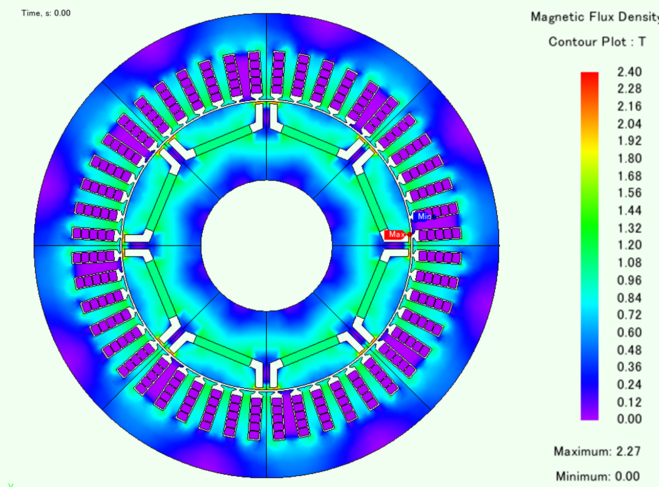
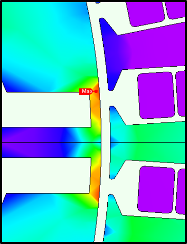
The left image is the magnetic flux density distribution across the motor geometry at a specific time point. The right image is a zoom-in, which shows a hot spot marked as Max, indicating the area with peak flux density, likely near the tooth tips or rotor edge. These visual plots help us validate electromagnetic performance beyond the usual current and torque waveforms.
This type of simulation is ideal for validating current ripple, NVH sensitivity, and control tuning under real-world conditions. While SIMBA is handling circuit and control simulation, JMAG simultaneously solves and logs field data. This combination of waveform data in SIMBA and field data in JMAG gives complete visibility into motor performance both globally and locally.