PMSM Inverter Drive
This ciruit shows a motor drive example composed of one inverter and one PMSM (permanent magnet synchronous machine) with the following settings:
- a DC input voltage of 500 V
- a switching frequency of 5 kHz
- a speed reference of 200 rpm represented by a ramp
Model
In this model, all components are ideal.
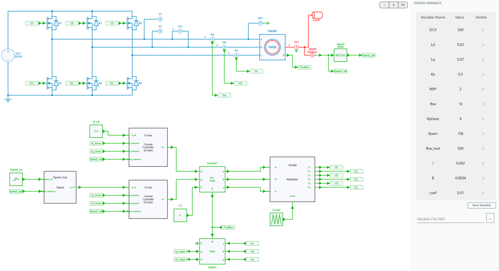
Some parameters values have ben encapsulated into the Design Variables windows in order to easily manage them by the user. Anyone can change those values and understand the impact of such modifications into the design.
First part of the circuit is composed of a DC voltage input source of 500 V + a 3-phase inverter circuit for driving the motor.
The 3-phase inverter allows to convert DC signals into AC such as current and voltage.
The second part is composed of PMSM + mechanical load taking into account only Linear Coefficient Torque.
The third part is the control stage including both speed loop & current loops with those specifications:
- speed reference control of around 200 rpm
- one PI controller for speed stage
- two PI controllers for current control stages (i_d & i_q)
- Inverse Park transformation block to transform dq signals into 3 signals abc.
- SPWM modulator strategy
Control & Modulation strategy
The control stage is composed one speed loop and two currents loops.
Speed Control Loop
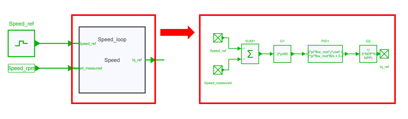
The speed loop uses a "piecewise linear" input block in order to set the speed reference.
Also one PI block has been added to this motion loop in order to extract the current reference Iq.
Indeed the output from the PI block is a torque command.
The block G2 was added to convert this torque command to the q-axis current command. By using this conversion block, the command q-axis current can be back-calculated once the command torque is decided.
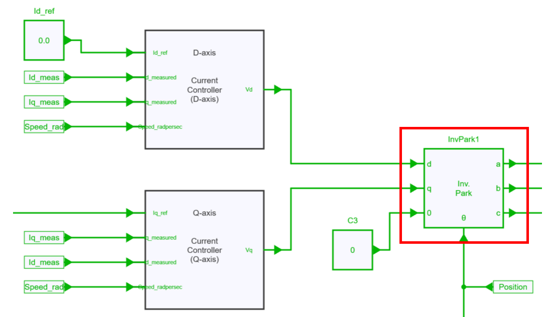
Current Control Loop
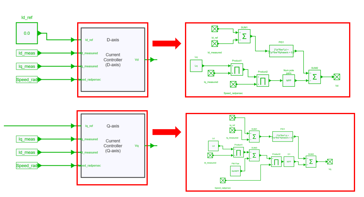
Then two current loops are designed into the 2 subcircuits "Current Controller (D-axis)" and "Current Controller (Q-axis)". Again two PI blocks are used for extracting the 2 signals Vd and Vq which will feed to the Invpark block.
The vector control uses in our case the InvPark block which allows to convert signals from dq frame (2D) into abc frame (3D).
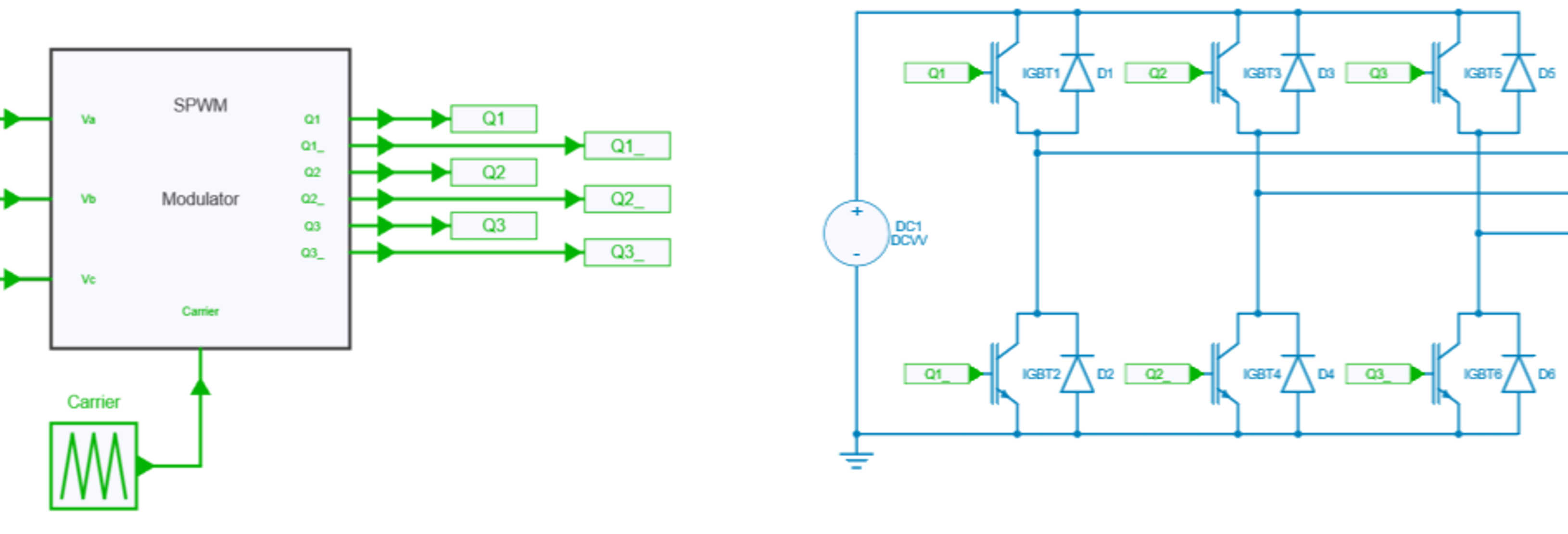
Modulation Strategy: Sine PWM
The inverter uses a sine PWM command to turn on / off the switches: this PWM is built by using a comparator block with 2 inputs: the triangular carrier waveform and a sinuoidal reference which comes from the dq / abc block. The ideal igbt models are directly connected to the logic PWM control signals provided by comparator blocks.
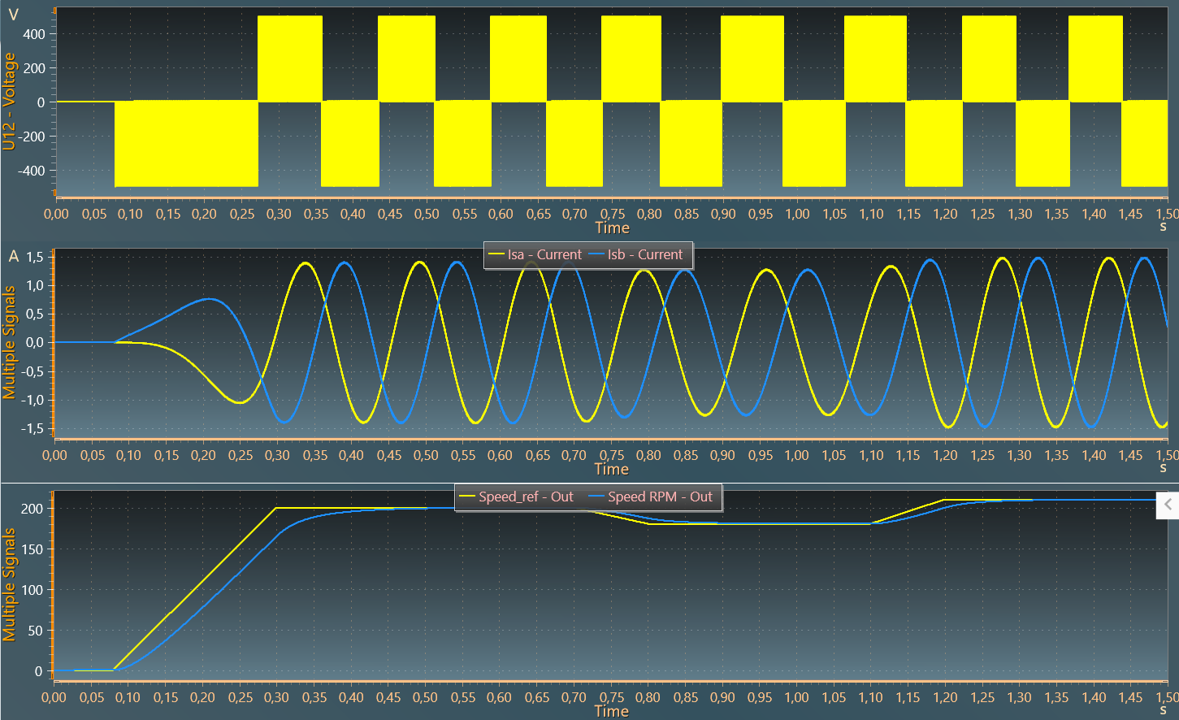
Simulation
The results below show the line-line voltage U_{12}, the current through the first and second phases and the reference and motor speeds.