AC Sweep Analysis
This tutorial covers Simba's AC sweep analysis feature.
This feature can help you to:
- Determine the frequency response of any system
- Calculate the transfer function of the system
- Design the controller
How to create and configure a testbench for AC Sweep?
To describe this feature, we consider the example of a DC-DC Buck converter (AC Sweep). Here we will configure a DC-DC Buck converter circuit for AC Sweep.
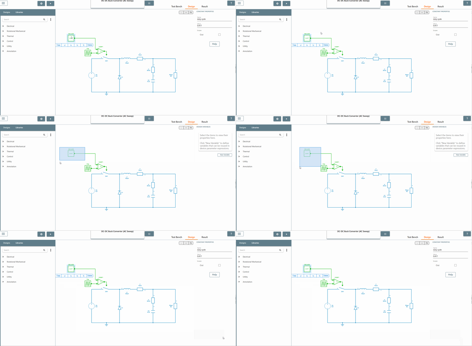
✔ Step 1: For the first step, identify the point in the circuit where the sinusoidal excitation source should be placed.
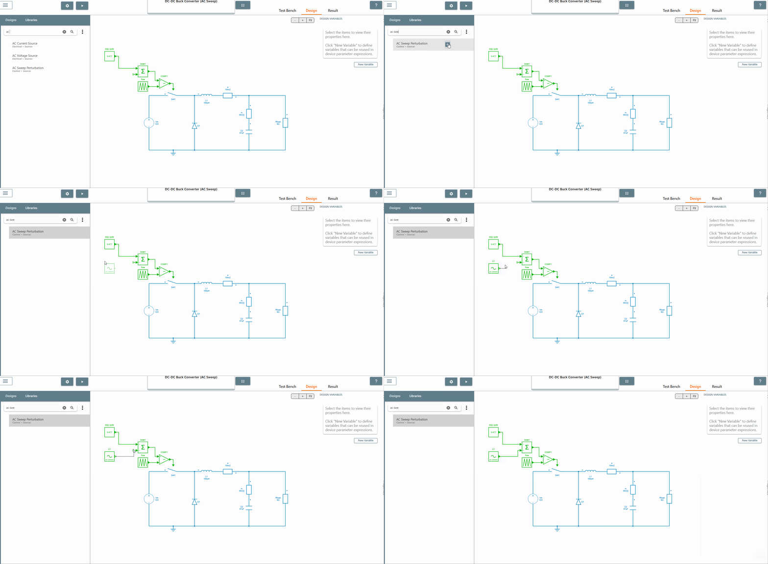
✔ Step 2: Place the AC sweep perturbation block from the library at the identified point.
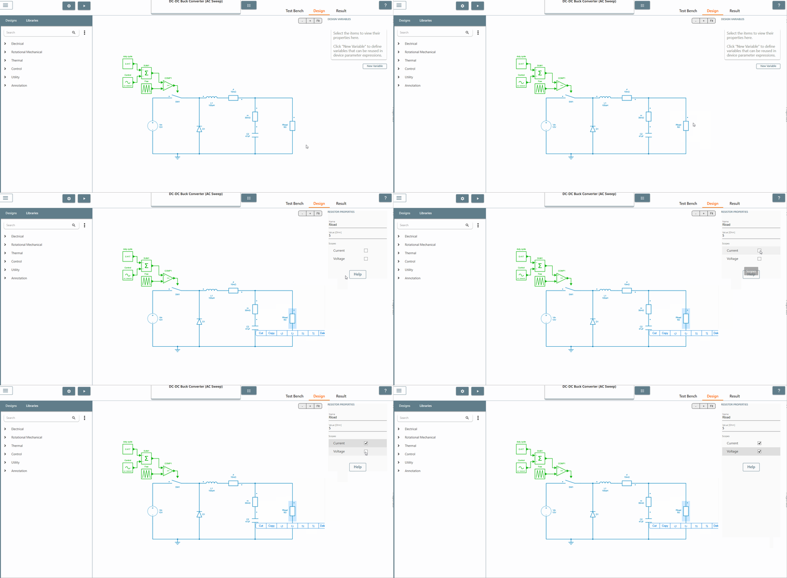
✔ Step 3: Select the scope of the element where the output is to be observed. The AC Sweep calculates the transfer function between the output scope and the perturbation. In this case, we select the scopes of the current and voltage of the resistor Rload.
✔ Step 4: Click on the 'Test Bench' tab to open the test bench interface. Then click on a plus sign followed by 'AC Sweep' to create an AC Sweep test bench.
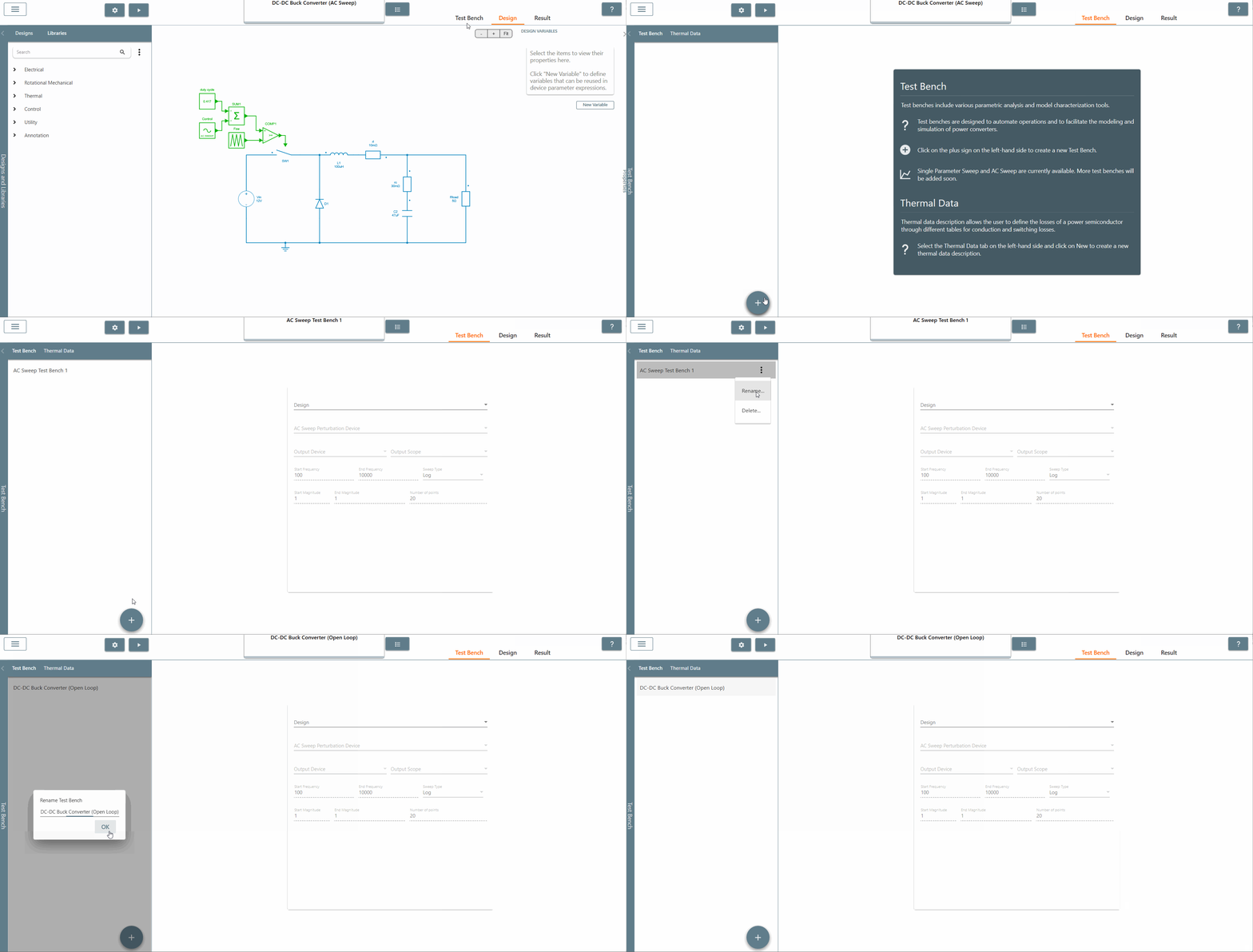
✔ Step 5: Once created, select the appropriate design from the 'Design' tab in which AC Sweep is to be performed. In this case, it is the Buck DC-DC converter (AC Sweep).
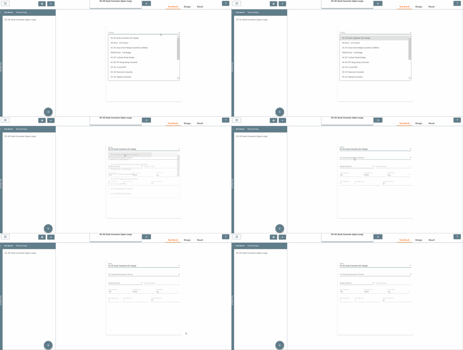
✔ Step 6: Also, select the AC Sweep perturbation device, the output device and output scope.
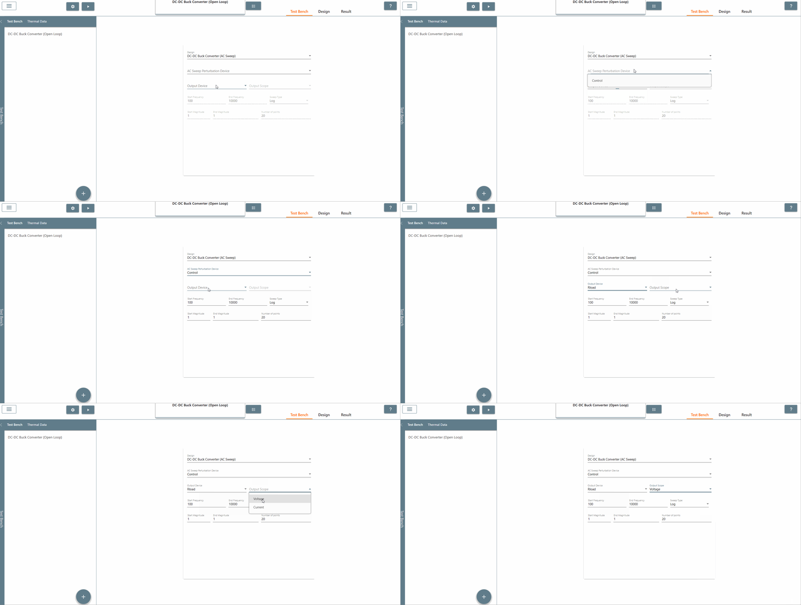
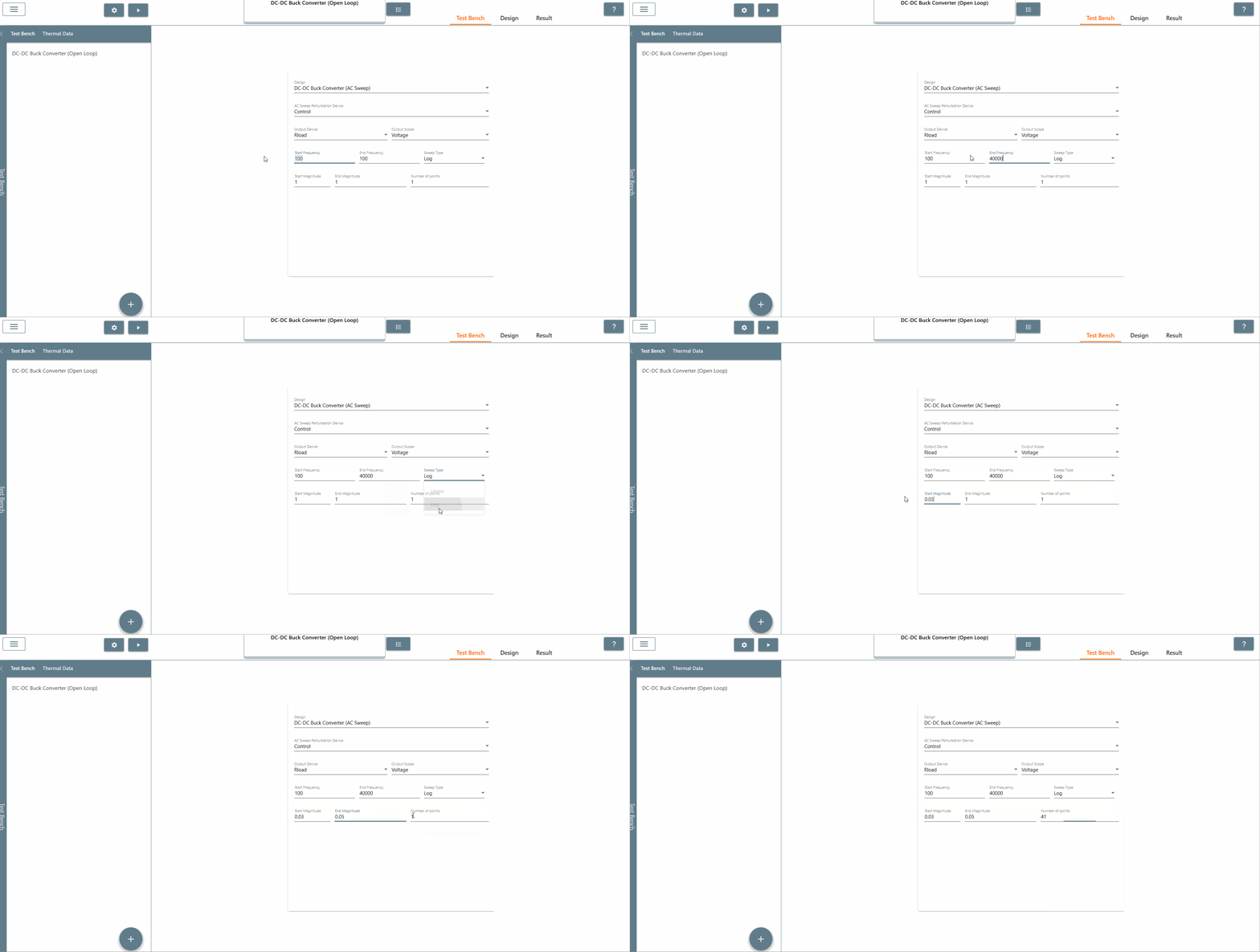
✔ Step 7: Select the start frequency, end frequency and scan type appropriately. In this case, the start frequency is 100 Hz, the end frequency is 40,000 Hz and the scan type is Logarithmic. It is recommended that the End Frequency is at most half the switching frequency.
✔ Step 8: Select the start amplitude, end amplitude and number of points appropriately. It is recommended that The end amplitude is slightly higher than the start amplitude because attenuation usually increases at higher frequencies.
✔ Step 9: Now click on the 'Run' button to run the AC Sweep and check the results under the Results tab.
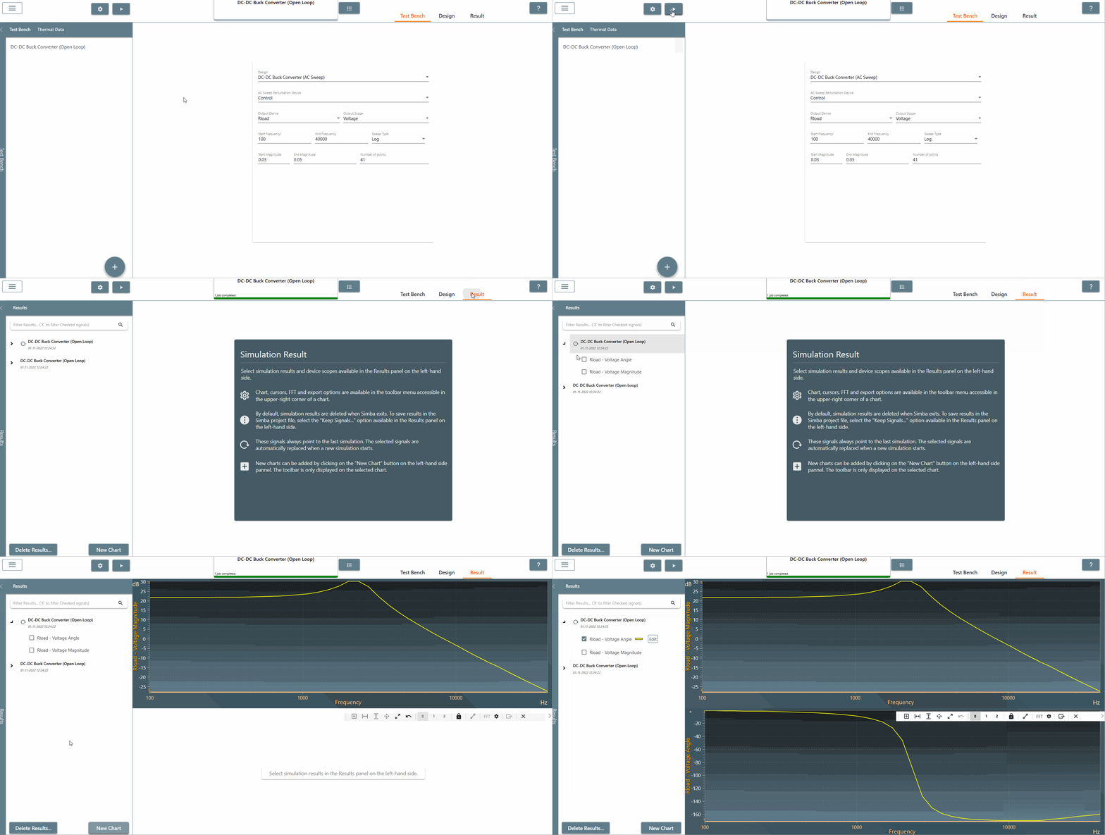 .
.
This concludes the creation of the AC Sweep circuit as well as the configuration of its test bench.