DC-DC Phase Shift Full Bridge
This example shows a Phase-Shift Full Bridge converter with:
- an input voltage of 400 V,
- an output voltage of 100 V,
- a power of 5.3 kW.
Phase-Shifted FullBridge (PSFB) converters are widely used in medium to high power applications where high DC voltage needs to be stepped down and isolation is required. These converters are similar to conventional full-bridge DC-DC converters, but with the added benefit of phase shift control, which enables efficient power conversion.
The PSFB consists of four power electronic switches, an isolating transformer with two secondary windings and rectifying diodes to form a centre-tapped full-wave rectifier, commonly used for low ripple AC to DC conversion. The converter and its control circuit are shown below:
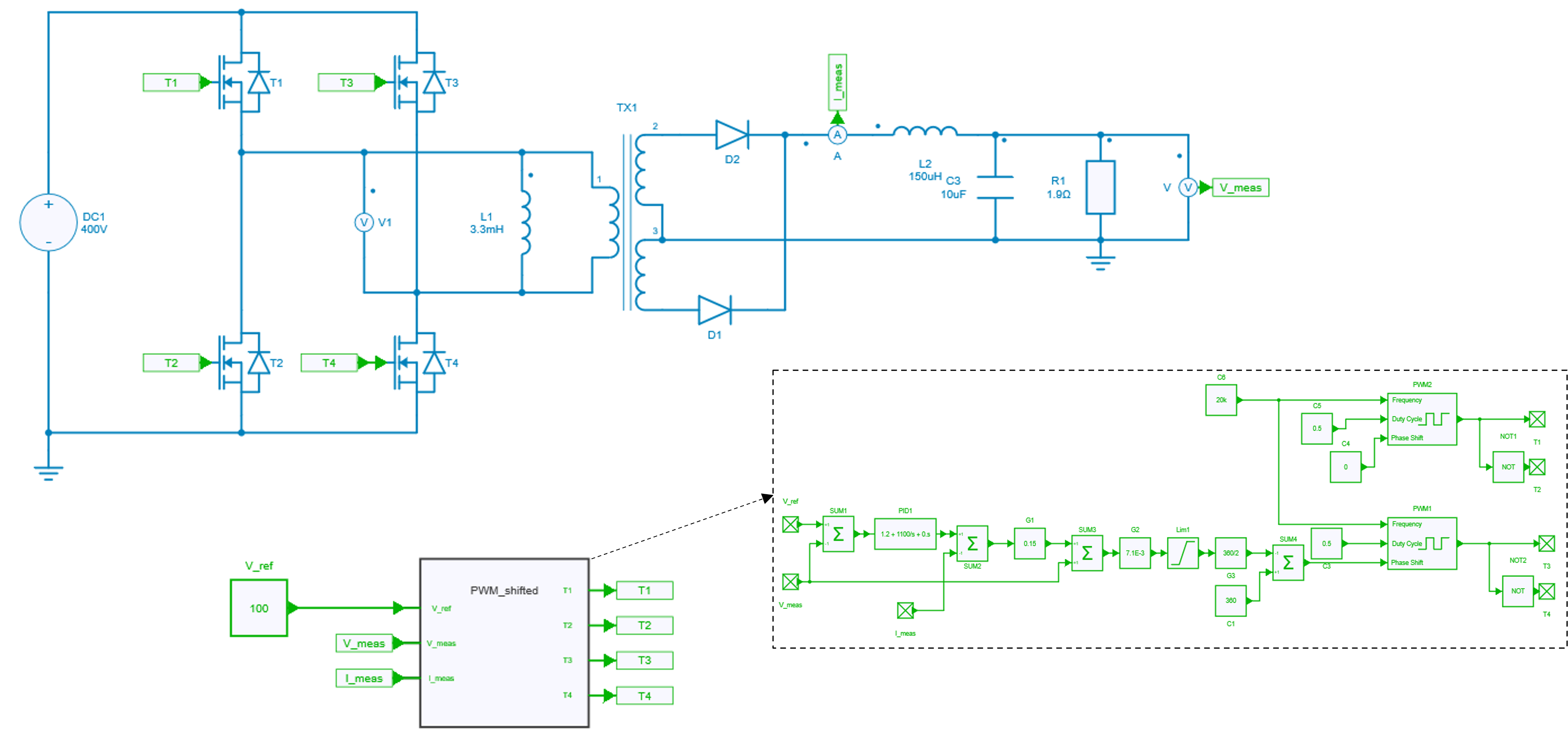
Model
Phase-shift PWM
Each switching cell is driven with a duty cycle of 50%. The control signal of the phase-shifted switching cell is created from the duty cycle reference according to the following formula:
The resulting phase shift is then fed to the Phase Shift input of the Controlled PWM Generator block. A tutorial demonstrating the functionality of this block can be found here.
Voltage loop
The voltage loop consists of a classic PI controller.

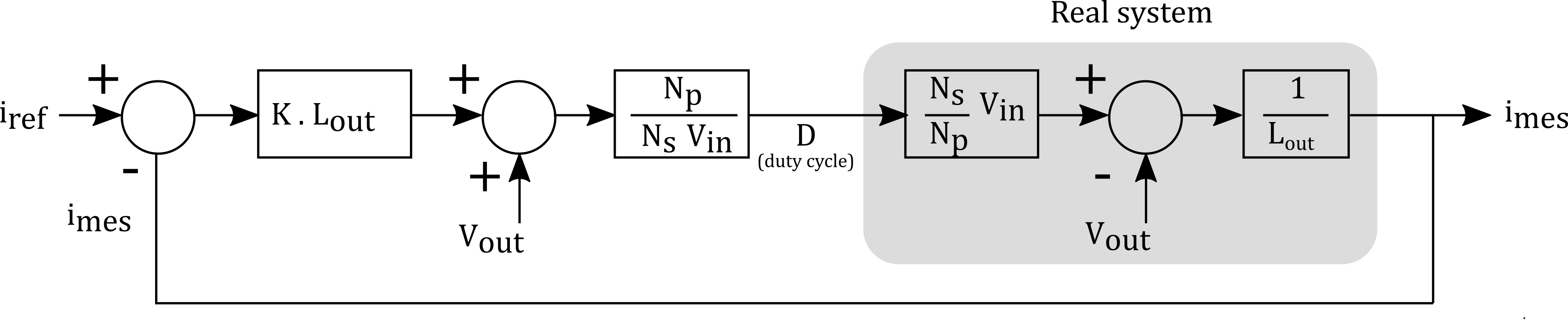
Current loop
The current loop implements an output voltage compensation to simplify the open-loop transfer function and to only keep the integrator behavior of the inductance. A simple gain correction can then be used.
Simulation
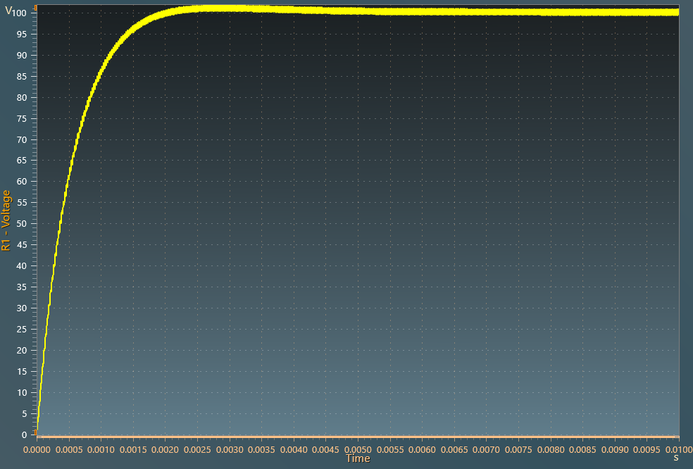
The results below show the output voltage across R1 resistor with a V_{ref}=100~V:
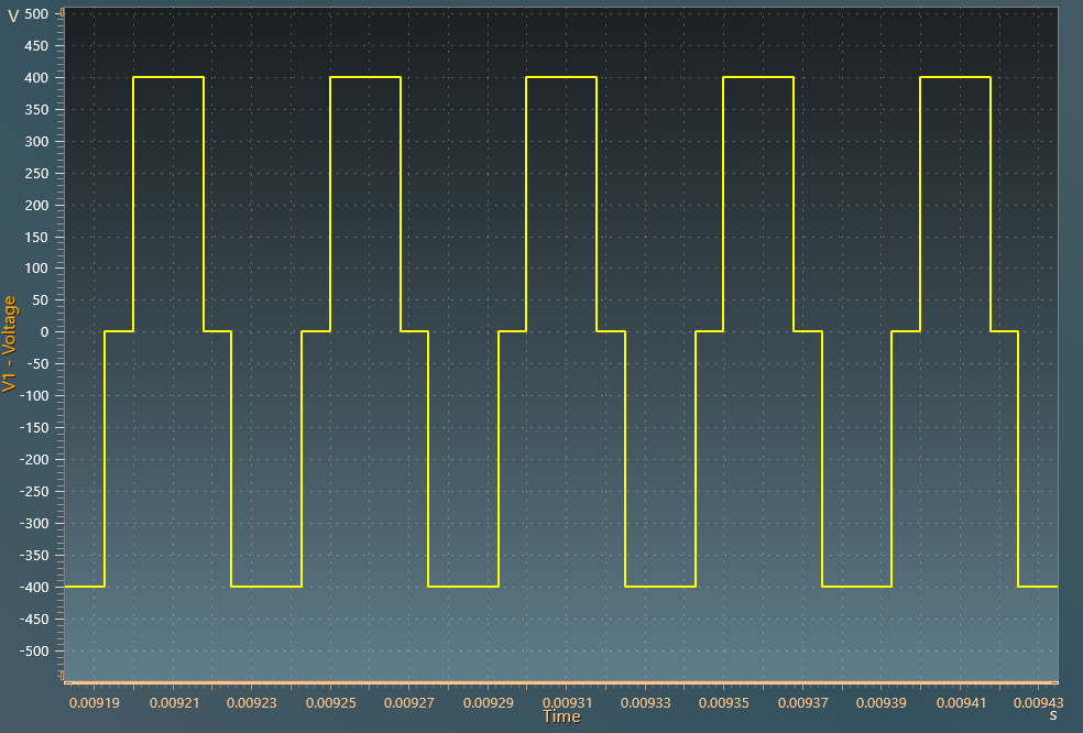
The results below show the voltage V1 across the primary winding of the transformer with a V_{ref}=100 V: