Modeling Coupled Inductors
This tutorial explores the element which models coupled inductors.
This element can help you:
- to model interleaved topologies which use coupled inductors to reduce the design of the magnetic component,
- or to model non-ideal transformers such as in a flyback converter.
Let's show this from an interleaved buck converter with two coupled inductors.
Building the circuit
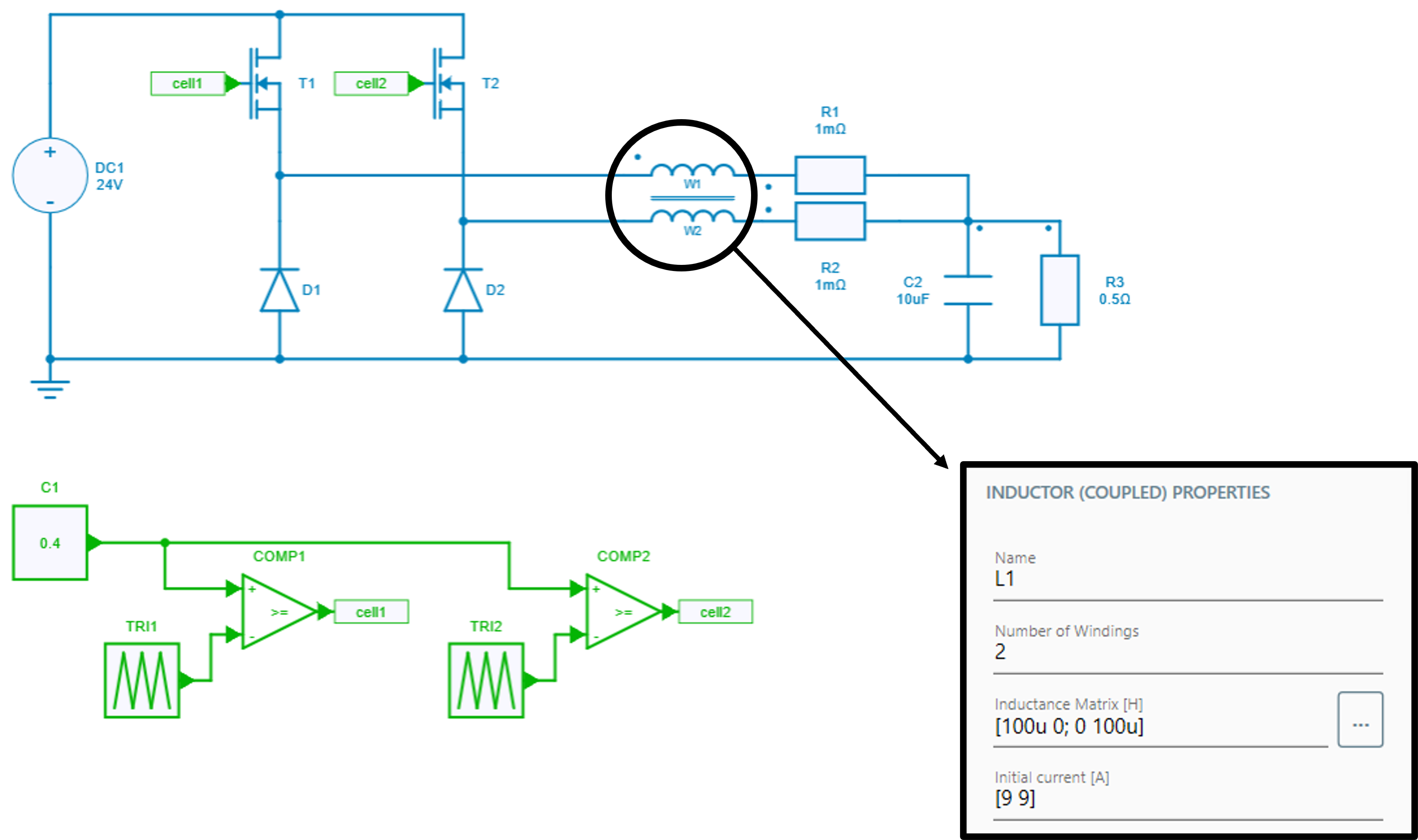
✔ Step 1: First, let's start here with this circuit which models two switching cells from a dc voltage source of 24 V. Each cell switches at 100 kHz and are phase-shifted of 180 degrees.
✔ Step 2: These two switching cells are then connected to:
- the coupled inductor element,
- some internal resistors of 1 m\Omega which help to stabilize the waveforms,
- an output capacitor of 10 \mu F,
- a load resistor of 0.5 Ω.
Self-inductance and mutual inductances
In the coupled inductor element, we have to define the self-inductance and the mutual inductances which define the coupling, as shown below.
Indeed, the coupled inductor element is defined with a matrix of dimension 'n' corresponding to the number of windings. The diagonal of matrix contains the self-inductance terms and the other terms are the mutual inductances between the different windings (see documentation for more information). Let's remind the mutual inductance terms M_{i,j} can be linked with the coupling factors K_{i,j} with the following relation:
In other words:
- a mutual inductance of 0 H means that the coupling factor is also 0 and that inductors are fully uncoupled;
- whereas a coupling factor of 1 (which leads to a mutual inductance equal to the square root of the self-inductances), means the inductors are perfectly coupled which leads to an ideal transformer.
Caution
Note that this case should be avoided with this element of coupled inductors as the matrix will be singular and cannot be inverted by Simba’s solver. In this use the ideal transformer component instead.
Simulation with a mutual inductance equal to 0
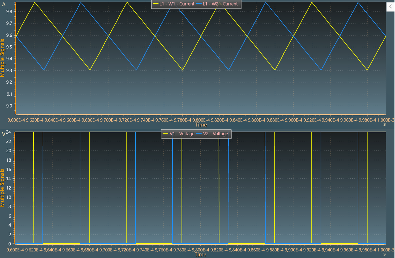
✔ Step 3: In order to watch the coupling influence, let's try a first simulation with a mutual inductance of zero Henry. Therefore, in the matrix of this coupled inductor element are set a self-inductance of 100 \mu H and a value of 0 H for the mutual inductance. Let's add two voltage meters to get the output voltage of each switching cell and let's also select the winding current scopes.
For the simulation parameters, an end time of 1 ms is enough and the minium time-step can be reduced to 10 ns*. In this case, when watching the simulation results, we can recognize for the winding currents, classical triangular waveforms which are phase-shifted of 180 degrees.
Simulation with a mutual inductance equal to -0.8
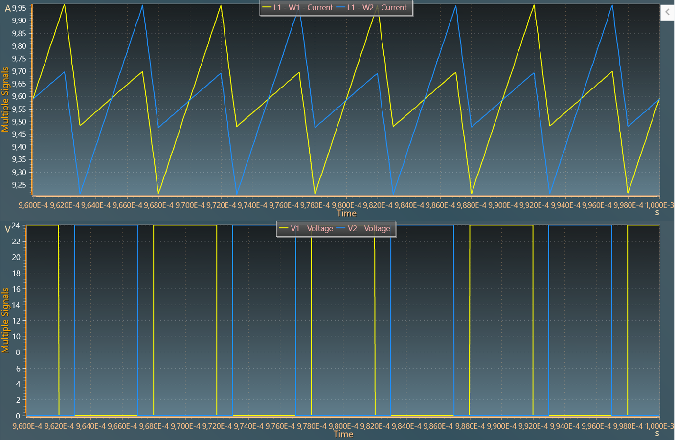
✔ Step 4: Now, let's do a simulation with a negative mutual inductance of -80 uH which corresponds to a coupling factor of 0.80.
With this new values, we can notice the slight modification of the current waveforms:
- a global "apparent switching frequency" which has been multiplied by 2,
- a little increase of the current ripple as the inductance per phase - directly linked to the leakage inductance - decreases when the coupling factor increases.
In the case of this interleaved buck topology, an appropriate compromise between coupling and leakages can help to reduce the current ripple at the switching frequency.
This benefit is also explained in the "interleaved buck" application example and it can lead to a design reduction of the inductors and the output filter.
This concludes this tutorial on exploring the element to model coupled inductors.