Electric Vehicle Battery Charger
This test case shows an Electric Vehicle Battery Charger (EVBC) comprised of a full bridge rectifier, an interleaved boost, and a LLC with the following settings:
- an AC input voltage of 110 V at 60 Hz
- multiples switching frequency at different stages
- an average output voltage of 210 V
- a power transfered of 291.9 W at the output resistor
This EVBC case demonstrates SIMBA's ability to simulate circuits composed of multiple high frequency switching converters requiring very small time steps.
Model
In this model, the mosfets with diodes have been chosen to get a more realistic behavior.
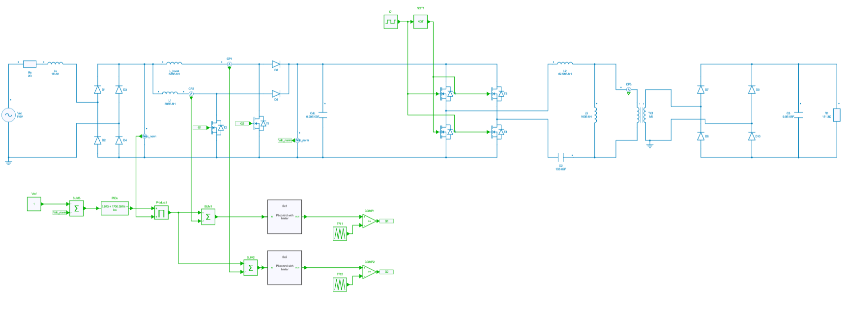
First stage
The first part of the circuit is composed of an AC voltage input source of 110 V + a full bridge rectifier.
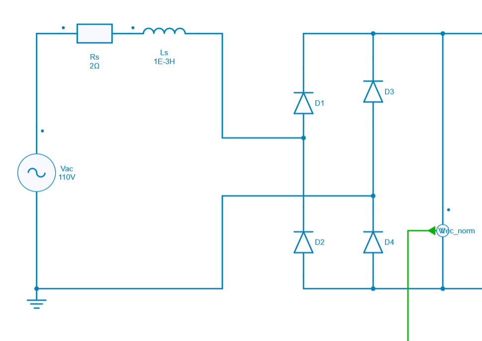
The goal of this circuit is to convert AC voltage into pulsating DC voltage. This type of converter is mainly used for power supplies.
Second stage
The second part of the circuit is composed of an interleaved PFC boost converter.
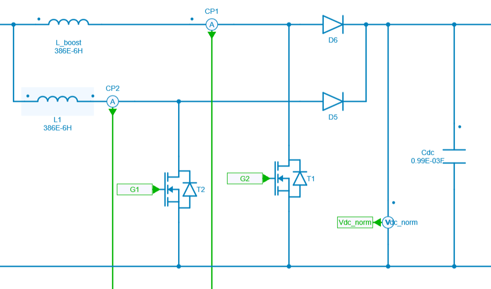
The capacitor Cdc is the DC link between stage 2 and 3.
Interleaved boost PFC is the most common topology for power factor correction. This topology uses a boost converter in addition to a rectifying diode bridge that converts the AC voltage to DC voltage. Then the boost converter steps the voltage up to a higher value. This reduces the output voltage ripple while shaping the current into a sinusoidal wave.
Power factor correction can be achieved using just one boost converter, but often two or more converters are connected in parallel, with a phase shift between the converters. This is called interleaving, which improves efficiency and reduces the input current ripple.
Interleaved PFC usually operates in critical conduction mode (CrCM) and provides some benefits such as: the use of smaller components, better thermal performance, low current ripple.
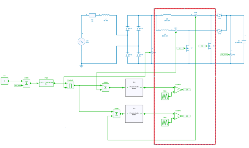
Third stage
The third part of the circuit is composed of an LLC resonant converter. This stage has two full bridge circuits separated by an isolation transformer. The transformer ratio is set for nominal operating voltage.
The resonant tank gain is function of resonant elements (L_2, L_3 and C_2), load (R_1) and switching frequency.
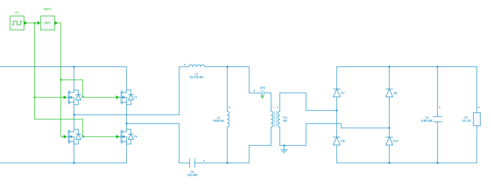
The goal of this isolated dc-dc converter is to charge the voltage battery.
By consequent, this LLC converter is switched at high frequency and requires a topology with soft switching in both directions.
Control stage
Several close control loops have been designed for the interleaved PFC boost part with those specifications:
- Outer voltage loop composed of one PI controller for regulating output voltage of PFC boost Vdc_norm.
- Inner current loops composed of two PI controllers for regulating current through each mosfets T1 and T2.
- PWM generation with comparator block for turning on/off the mosfets T1 and T2.
Control & Modulation strategy for the interleaved PFC Boost
Control
The control stage is composed one voltage loop and two currents loops.
Outer Voltage Loop
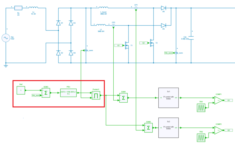
The outer voltage loop uses a Vref input constant block in order to set the voltage reference. Its value is equal to 1 because we do normalize the voltage Vdc_norm with a gain of: 1/175, so it needs to be properly scaled.
Also one PI block has been added to this voltage loop in order to extract the reference for the 2 inner current loops.
Inner Current loop
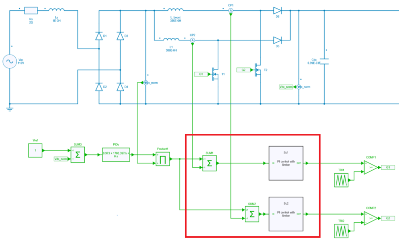
One current loop has been designed for each mosfets T1 and T2. Those 2 current loops are encapsulated into the 2 subcircuits Sc1 and Sc2. Again two PI blocks with anti wind-up are used for extracting the 2 reference signals which will feed the comparator blocks comp1 and comp2.
Modulation strategy
The interleaved PFC boost uses a PWM command to turn on/off the mosfets T1 and T2: each mosfet gate is directly driven by a comparator block which uses a triangular carrier waveform and a signal which respectively comes from the output of each inner current loop modelled in Sc1 and Sc2 subcircuits blocks.
Simulation
The AC input voltage is 110 V.
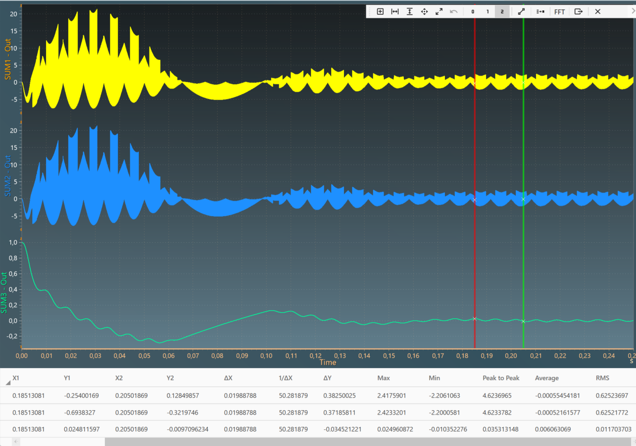
The results below show the signals at the output of each stages:
- Output voltage of the full brudge rectifier,
- Output voltage of the interleaved PFC boost,
- Output voltage of this battery charger accros the load R_1.
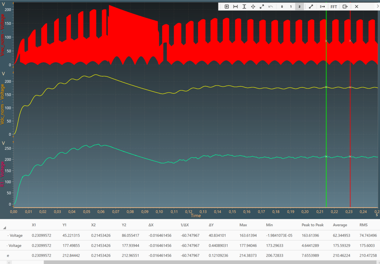
The average voltage accross R_1 could be computed easily and its value is around 210 V and the system is quite stable at steady state even though few oscillations are there. Of course those could be mitigated.
The currents of the LLC stage can also be plotted:
- of the inductor of the resonant tank i_{Ls},
- of the magnetizing inductor i_{Lm},
- the secondary current seen from the primary of the transformer (n x i_2).

At lats, more signals could also be highligted such as:
- the error signal measured between Vref and Vdc_norm (outer voltage loop)
- the error signal corresponding to the input signal of inner current loop Sc1
- the error signal corresponding to the input signal of inner current loop Sc2
The average could also be easily computed and its value is close to 0 as required.
Reference
H. Chalangar, T. Ould-Bachir, K. Sheshyekani and J. Mahseredjian, "Methods for the Accurate Real-Time Simulation of High Frequency Power Converters," in IEEE Transactions on Industrial Electronics, doi: 10.1109/TIE.2021.3114706.