Buck-boost Converter
This example shows a DC-DC Buck-Boost converter with:
- an input voltage of 8 V,
- an output voltage of 24 V (depending on duty cycle),
- a power of 114 W transferred ( P_{output}=P_{input} ).
A Buck-Boost converter is a switching power supply operating such as a DC-DC Step-Down converter or a DC-DC Step-Up converter with a reverse polarity and depending upon the duty cycle value.
Model
In this model, all components are ideal.
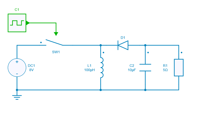
When the switch is ON (closed), it represents a short circuit ideally offering zero resistance to the flow of current so all the current will flow through the switch and the inductor and back to the DC input source. In that case the inductor stores charge during the time the switch is ON.
However when the switch is OFF (opened) the polarity of the inductor reverses so that the current flows through the load and through the diode and back to the inductor. In concludion the energy is transfered from inductor to capacitor + resistor when switch if off.
Switch control
The switch model can be directly connected with a control signal. For this control, we use a PWM block with an amplitude of 1, a duty cycle of 0.75 and a frequency of 100 kHz.
Here are the values of the other components :
- inductor L1: 100 µH and initial current = 0 A,
- capacitor C2: 10 uF and initial voltage = 0 V,
- resistor R1: 5 Ω,
- diode D1: Rd = 0 Ω and Vd = 0 V.
Simulation
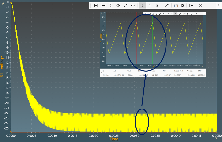
The results below show the output voltage across R1 with a duty cycle= 0.75. A zoom shows a measure of the average value of this voltage : -23.94 V.
The results below show the output voltage across R1 with a duty cycle= 0.5. A zoom shows a measure of the average value of this voltage : -7.98 V.
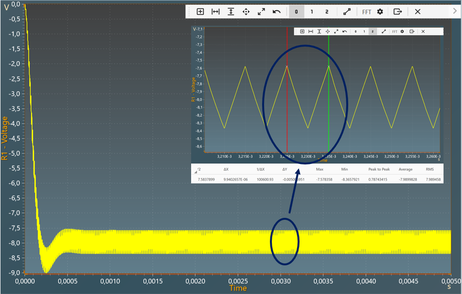
The results follow the equation: V_{out} = - V_{in} \times \frac{D}{1-D}
With:
- D: Duty cycle
- V_{in}: Input voltage
- V_{out}: Output voltage