Boost Converter
This example shows a DC-DC Boost converter with:
- an input voltage of 10 V,
- output voltage of 20 V for duty cycle D = 0.5,
- a power of 16 W transferred ( P_{output}=P_{input} ).
A Boost converter is a class of switch mode power supply (SMPS) which is a DC-DC Step-Up converter that steps up voltage from its supply to load while stepping down the current depending upon the duty ratio.
Model
In this model, all components are ideal.
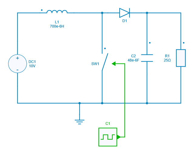
When the switch is ON (closed), the diode in the circuit is in reverse biased condition and the energy is transferred from the input supply to the inductor. Hence, the inductor stores the energy during the switch ON period.
However, when the switch is OFF (open), the diode in the circuit is in forward biased condition and the polarity of the inductor reverses so that the energy transfer takes place from the inductor and source to the load.
In conclusion, the energy is transferred from inductor and the input dc source to the load when the switch is off.
Switch control
The switch model can be directly connected with a control signal. For this control, we use a PWM block with an amplitude of 1, a duty cycle of 0.5 and 0.6 respectively, and a frequency of 30 kHz.
Here are the values of the other components :
- Inductor L1 : 700 µH,
- Capacitor C2 : 48 µF,
- Load R1 : 25 Ω.
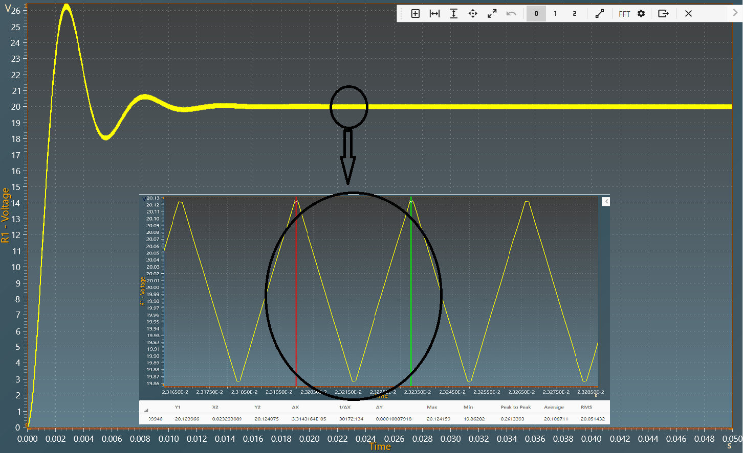
Simulation
The results below show the output voltage across R1 with a duty cycle= 0.5. A zoom shows a measure of the average value of this voltage: 20 V.
The results below show the output voltage across R1 with a duty cycle= 0.6. A zoom shows a measure of the average value of this voltage : 25 V.
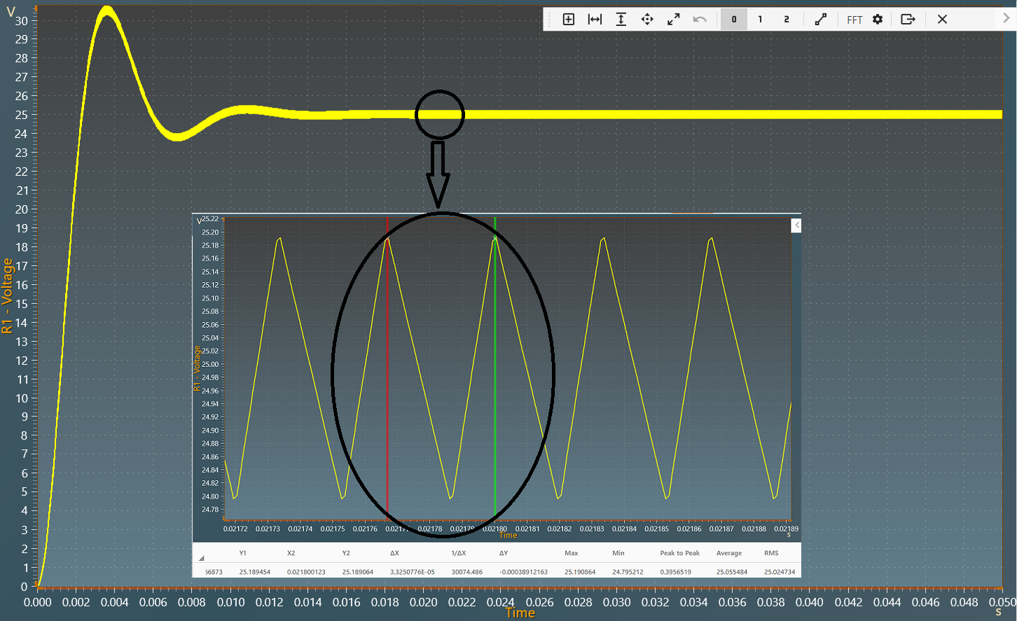
The results follow the equation: V_{out} = \frac{V_{in}}{1-D}
With:
- D : duty cycle
- V_{in}: Input voltage
- V_{out} : Output voltage