Modulation Strategies of a Motor Drive Inverter (including JMAG-RT model)
Download python script for simulation
Download python script for plotting
Download Python Library requirements
Motor drive inverter model
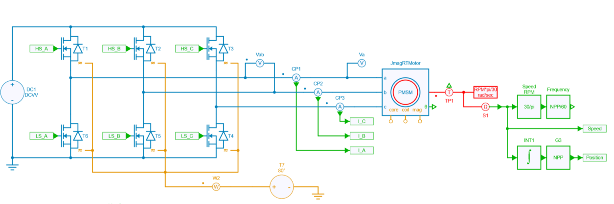
Inverter & motor model in SIMBA
The motor drive inverter model consists of a 3-phase 2-level voltage source inverter (VSI) that supplies a JMAG interior permanent magnet synchronous motor (IPMSM). The IPMSM is connected to a load that imposes a constant speed, meaning that the motor must be able to produce enough torque to maintain the desired speed.
Info
JMAG has the capability to provide real accurate machine model data by the use of .RTT file. Thus any JMAG user can extract .RTT file and implement a complete drive system in SIMBA. For more information about JMAG-RT, refer to JSOL website. IPMSM's specifications are summarized below:
| Motor specifications | |
|---|---|
| Model | withHF_4000rpm20Nm |
| Model Name | IPMSM |
| Max. Power Output | 80 kW |
| DC Voltage | 600 V |
| Max. Current | 250 A |
| Number of Poles | 8 |
| Number of Slots | 48 |
| Core material | 35JA300 |
| Magnet | NdFeB, Br=1.2 (T) |
Control & Modulation Strategy
A DQ control has been implemented (described in another example allowing to realize the closed control loop for driving the motor drive inverter.
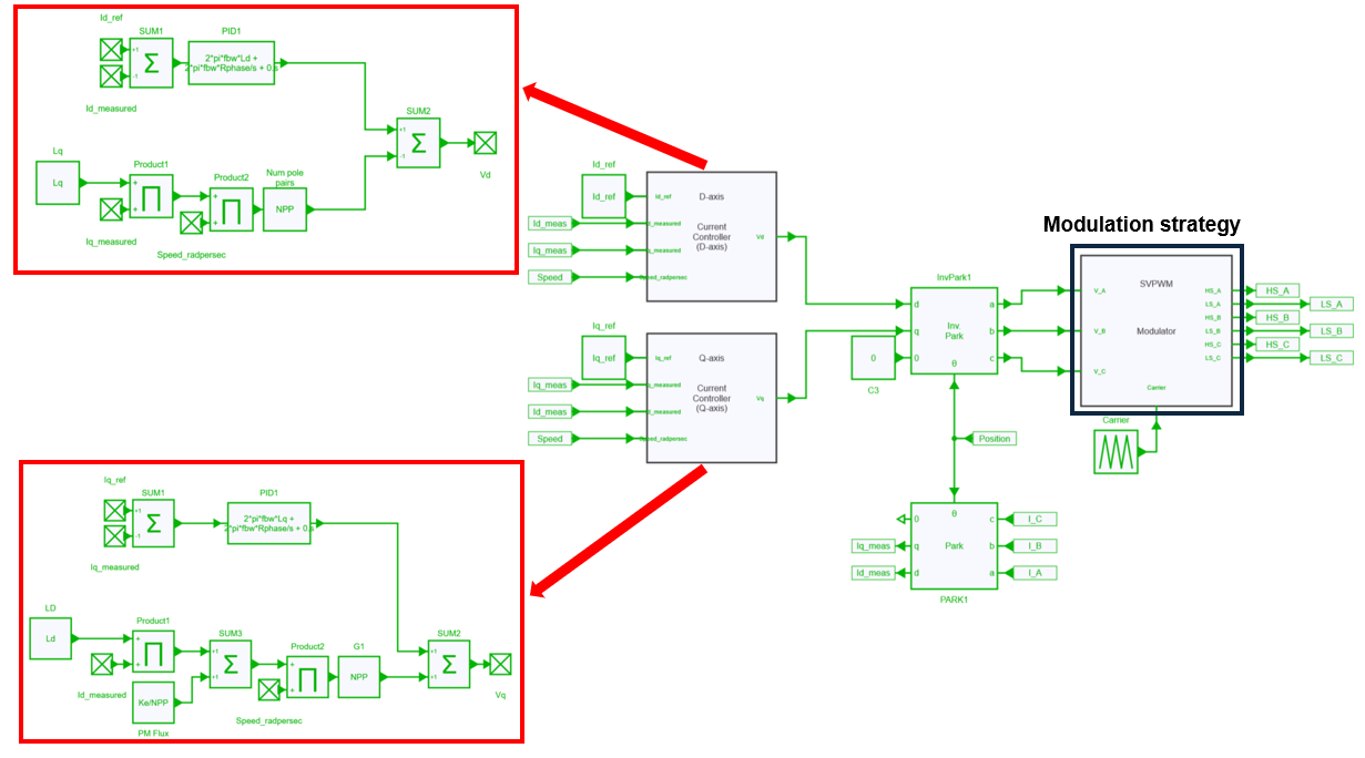
Several modulation strategies have been considered to evaluate their influence on losses of both inverter (conduction and switching losses) and motor (iron and copper losses). Different switching frequencies have also be used (20, 40 and 60 kHz). Therefore, a relation between frequency and modulation strategy can be easily highlighted.
In this traction motor drive system, 3 modulation strategies will be used:
- SVPWM: a "carrier-based" Space Vector PWM (also known as MIN-MAX modulation)
- SPVM: Sinus PWM
- DPWM: Discontinuous PWM
When opening the SIMBA project "modulation_strategies_motor_drive.jsimba" 3 designs have been created representing each modulation strategy mentionned above.
SVPWM
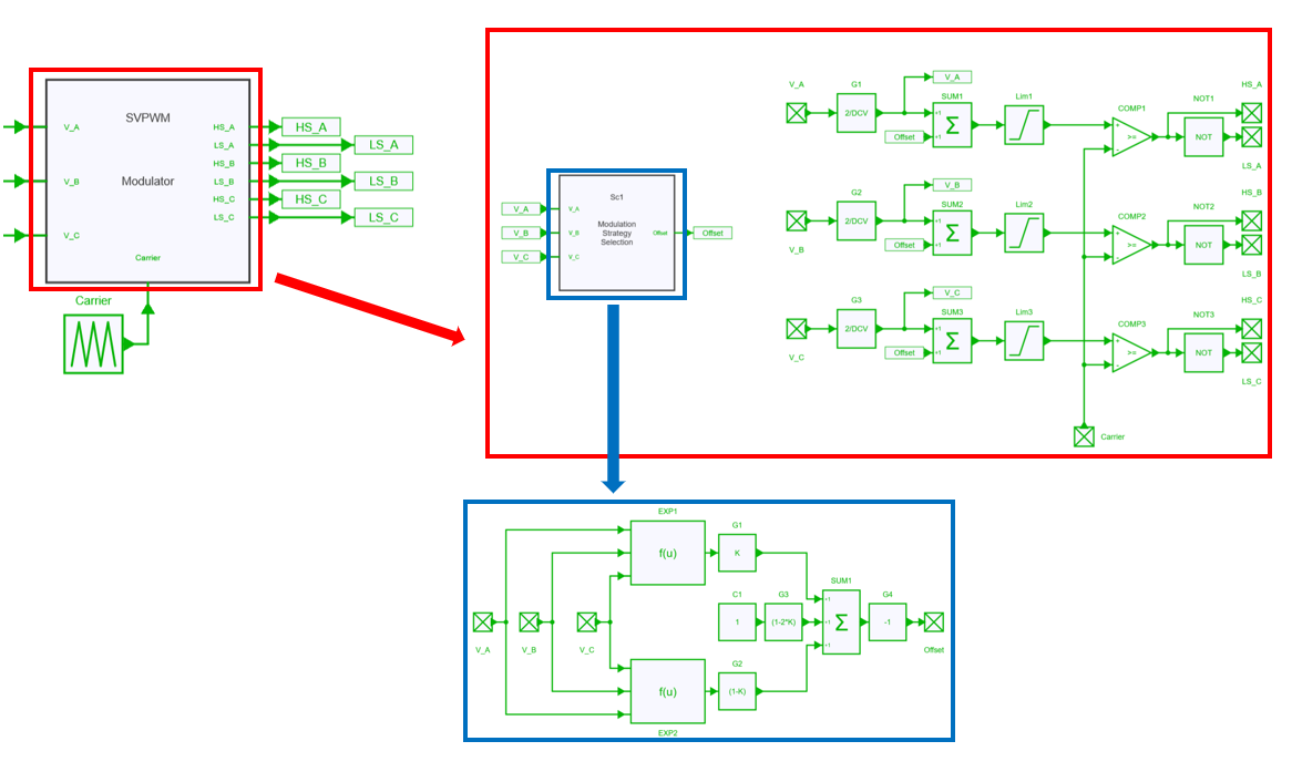
This modulation strategy offers a similar pattern as the space vector modulation and can be shown as a triangle-intersection or carrier-based implementation of the conventional Space vector modulation.
It is also known as the MIN MAX modulation strategy.
SPWM
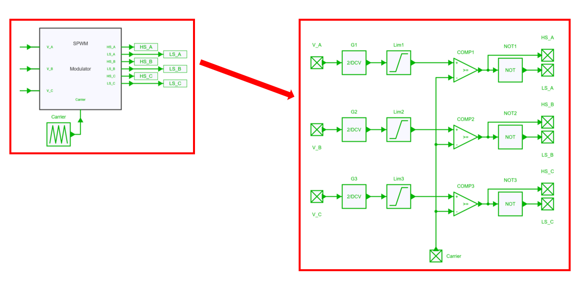
This Sine modulation (Sine PWM) is probably the simplest modulation strategy whereas the maximum modulation index is equal to 1.
DPWM
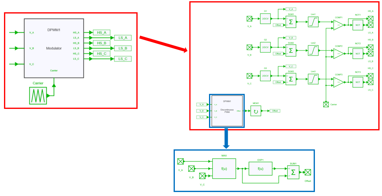
In DPWM modulation the phase leg is clamped 30° symmetricaly from maximal voltage. This method has low harmonic distortion characteristics.
Info
An existing example is already available for modulation strategies description here
Thermal modeling
To model the thermal performance of MOSFETs in an inverter, their package temperature is held constant and data is extracted from the .xml files provided by the manufacturer. In this particular case, Wolfspeed CAB006M12GM3 mosfets were used and can be downloaded here.
Main python script
The python script named modulation_strategies_motor_drive.py is used to perform simulations for various operating points and switching frequencies and finally display the losses according to each different scenario.
Let's consider the operating points mentionned below for performing the simulation:
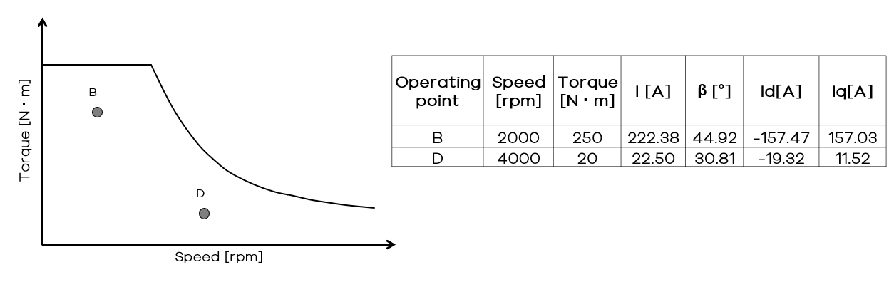
The python script aims to run a simulation at those 2 operating points, with different speed and torque levels (induced by different Id and Iq values).
Two loops have been considered into the script:
- one Speed loop to drive the motor at 2000 and 4000 rpm
- one Frequency loop (nested in the Speed loop) to modify the switching frequency at 20, 40 and 60 kHz.
The final goal is to obtain the losses of the complete drive (motor + inverter) in steady-state, plot and compare them for different modulation strategies and operating points.
In this example the motor losses are obtained thanks to the JMAG-RT model.
Results
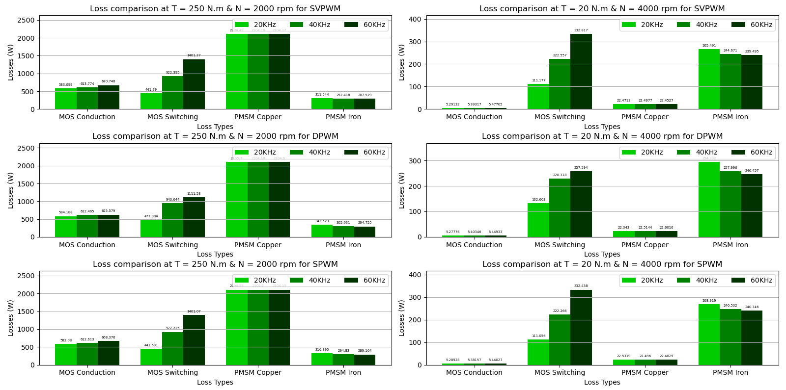
A second python script named modulation_strategies_motor_drive_plot.py is available to display results. A first figure shows results displayed as bargraphs (and thus the influence of the switching frequency) as shown below:
A second figure shows results displayed as histograms (and thus which losses are dominant) as shown below:
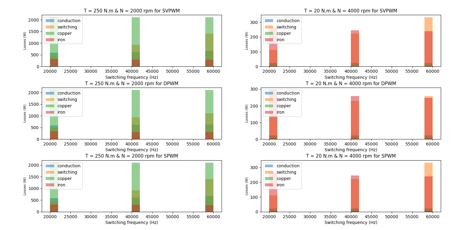
When comparing these figures, several conclusions can be provided such as:
At operating point B (high load & load speed: Torque = 250 N.m and Speed = 2000 rpm):
- device conduction losses & and especially copper losses become dominant,
- increasing the switching frequency between 20 and 60 kHz leads to higher losses of the overall system (mainly due to device switching losses)
At operating point D (low load & high speed: Torque = 20 N.m and Speed = 4000 rpm):
- iron losses become dominant,
- increasing the switching frequency between 20 and 60 kHz leads to lower losses of the entire system (mainly due to motor iron losses which decrease as the current ripple decreases)
For each operating points, SVPWM and SPWM provide very close results.
A combination of SIMBA and JMAG-RT leads detailed and fast loss evaluation of the entire drive system.