Flyback Converter
This example shows a DC-DC Flyback Converter with:
- an input voltage of 48 V,
- an output voltage of 12 V,
- a power of 24 W transferred to the output resistor.
The Flyback converter is in reality a power supply based on the principle of an inductive storage chopper, it is a static converter with a galvanic isolation between the input and the output. Its basic scheme is similar to a Buck-Boost converter in which the inductor is replaced by a transformer (actually two coupled inductances). The Flyback converter is generally used in power applications (LCD monitor, CRT TV, DVD player, ...).
Model
In this model, all components are ideal.
In the on-state, the switch is closed, the primary of the transformer is directly connected to the input voltage source. This results in an increase of the magnetic flux in the transformer. The voltage at the secondary boundaries is negative, blocking the diode. It is the output capacitor that provides the energy required by the load.
In the off-state, the switch is opened. The energy stored in the transformer is transferred to the load.
Transformer model
Two ways are proposed to model the transformer.
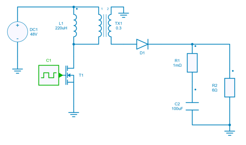
The first one includes a classical ideal transformer model as shown in the section above with :
- a turn ratio \frac{V_2}{V_1} = 0.3,
- a magnetizing inductor L_1 of 220 µH.
The second one proposes a transformer model in the magnetic domain (see SIMBA documentation on magnetic modeling to get more details about this approach) with two winding-gyrator components and a permeance component as shown below:
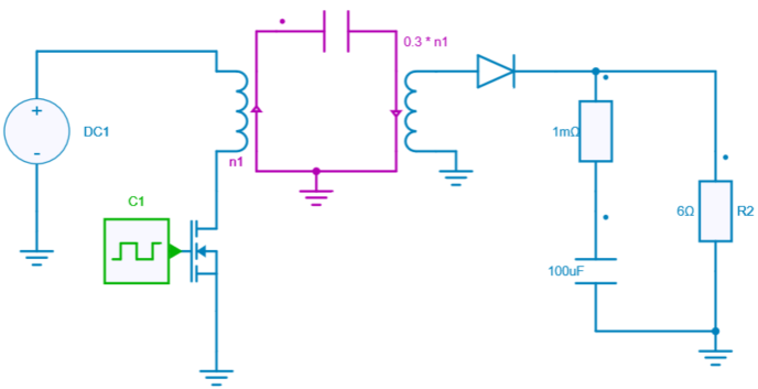
To get the exact same behaviour in both models, the following parameters are defined:
- the number of turns is respectively set to 30 and 9 for the primary and secondary winding,
- the permeance value is set according to L_1 value and to the ratio of the winding-gyrator component at the same side (i.e. the number of turns N_1 of primary winding):
$P = N_1^2 \times L_1$
Switch control
The mosfet model can be directly connected with a control signal. For this control, we use a PWM block with an amplitude of 1, a duty cycle of 0.455 and a frequency of 100 kHz.
Here are the values of the other components :
- capacitor C_2: 100 uF and initial voltage = 3 V,
- resistor R_1: 1 m Ω,
- resistor R_2: 6 Ω,
- diode D_1: Rd = 0 Ω and Forward voltage = 0 V,
Simulation
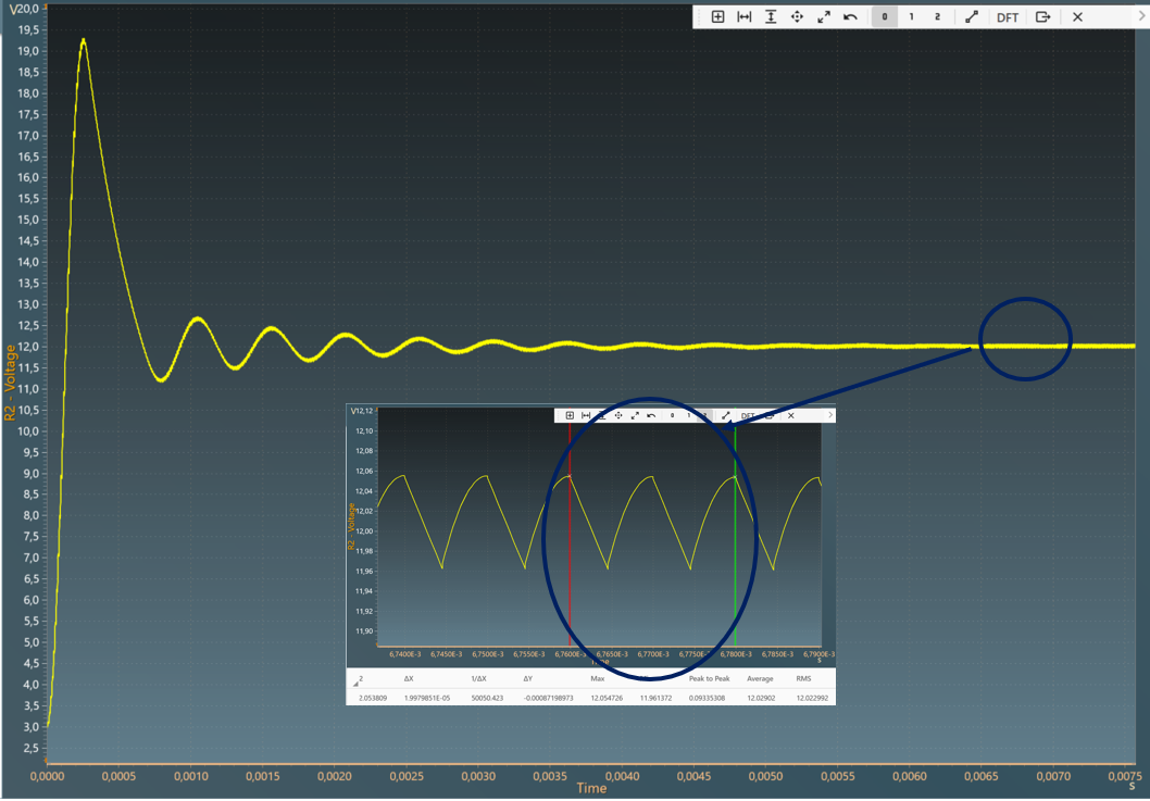
The results below show the output voltage across R2 with a duty cycle= 0.455. A zoom shows a measure of the average value of this voltage : 12 V.
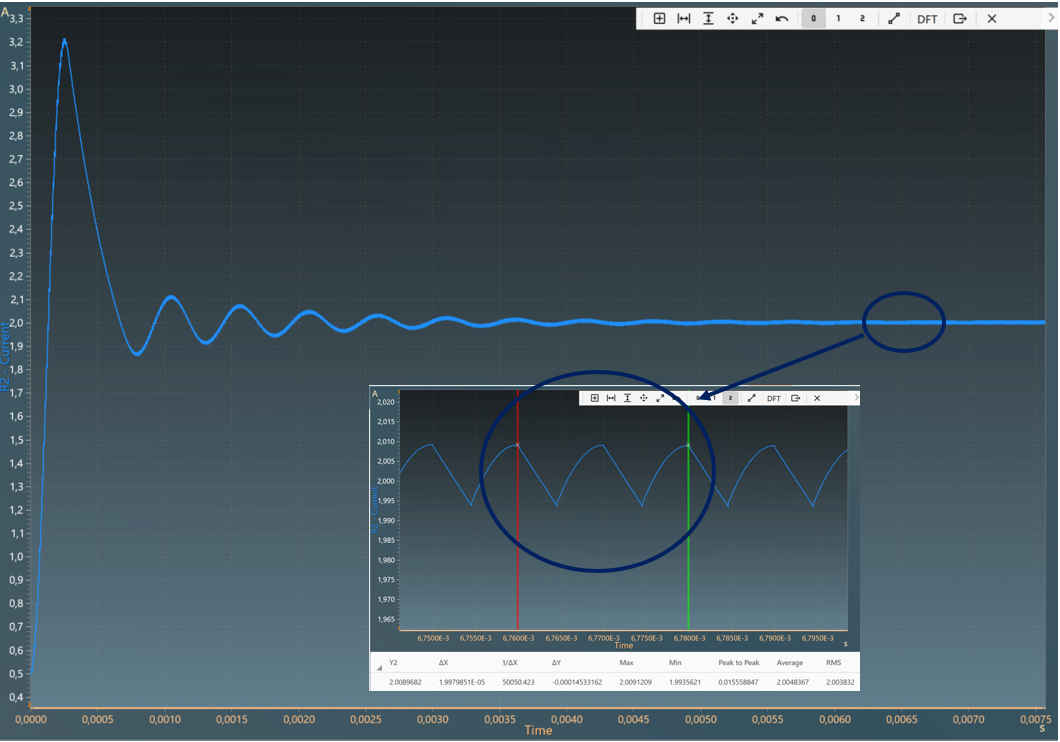
The results below show the output current through R2 with a duty cycle= 0.455. A zoom shows a measure of the average value of this current : 2 A.
The results follow the equation: V_{out} =\frac{N_2}{N_1} \times V_{in} \times \frac{D}{1-D}
with:
- D: Duty cycle
- V_{in}: Input voltage
- V_{out}: Output voltage
- N_2: Number of turns at secondary
- N_1: Number of turns at primary