AC-DC 3-phase Thyristor Rectifier
This example shows an AC-DC 3-phase controlled phase rectifier with:
- an AC grid voltage of 400 V and a frequency of 50 Hz,
- a DC inductive load,
- an output power of 29.9 kW for a delay angle of 0°.
With the parameter sweep feature available in the Test Bench tab, the influence of the delay angle can be evaluated with only one simulation.
Model
Electrical Top Model
The schematic below shows the electrical top model considered of this controlled phase rectifier. Thyristors are ideal components, the inductor value is 5 mH and the resistance value is 10 Ω.
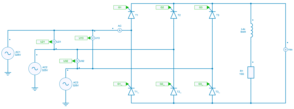
This electrical top model uses two design variables which are used in three-phase voltages sources and in the subcircuit of the delay angle control:
- AC grid frequency: fgrid,
- delay angle in degrees: delay_angle.
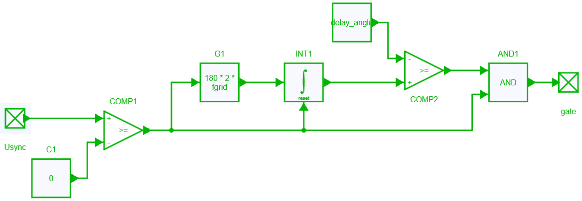
Model of the delay angle control
The schematic below shows the control of the delay angle. First, the synchronisation voltage is compared to zero to get the natural switching angle (of a diode bridge). From this natural switching angle, an integration is performed, then compared with the considered delay angle. When the integration result is above the delay angle value it will send the gate signal to the thyristor.
Simulation
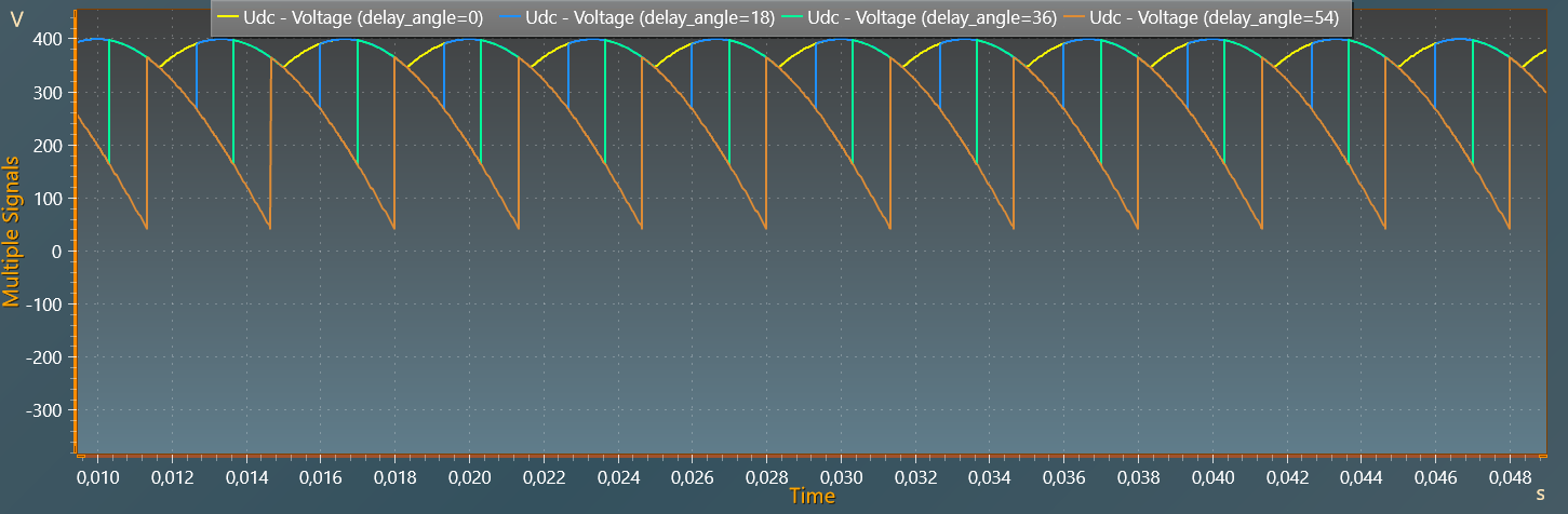
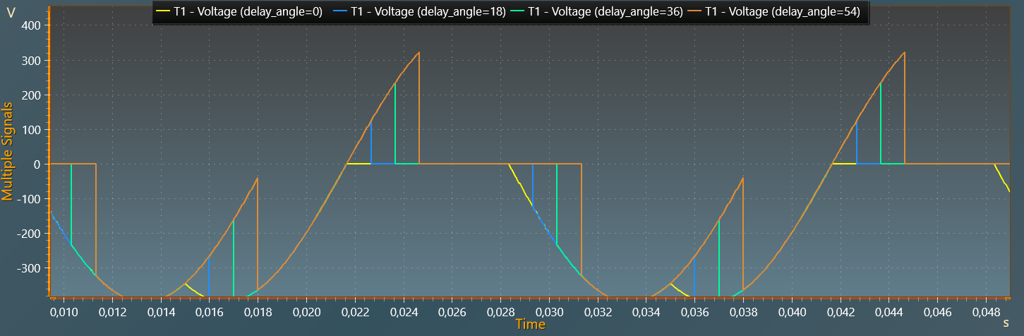
As mentionned in the introduction, a variation of the delay angle - using the parameter sweep feature - is performed from 0° to 54° with 4 values.
The figures below respectively show the DC output voltage and the thyristor for these different delay angles: 0°, 18°, 36° and 54°.