Three Phase inverter
This example shows a three-phase voltage source inverter with a sine Pulse Width Modulation (PWM) and the influence of the switching frequency on waveforms and frequency spectrum. The parameters of the circuit are the following:
- a DC input voltage of 800 V,
- a modulation index of 0.9,
- a reference frequency of 50 Hz,
- with a load of 3.87 Ω, 1.7 mH per phase,
- a switching frequency between 1.95 kHz.
The task of an inverter is to convert a DC input voltage into an AC output voltage whose amplitude and frequency can be adjustable. The modulation schemes employed to regulate the inverter have a significant impact on the efficiency characteristics of the device, including switching losses and harmonic reduction. Pulse width modulations (PWM) is a term used to describe a number of these schemes.
Model
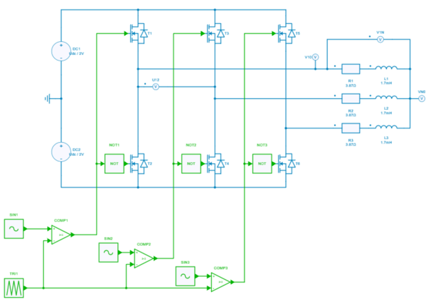
The models shows a three-phase voltage source inverter connected to an inductive load. The modulation is a sine Pulse Width Modulation (PWM).
Sine PWM control
The inverter has been controlled in this design using the Sinusoidal Pulse Width Modulation (SPWM) approach - one of the simplest PWMs - which directly controls the inverter output voltage and output frequency in accordance with sine functions. In this PWM approach, the switching states for each leg in the inverter are determined by comparing an sinusoidal AC voltage reference v_{ref} with a high-frequency triangular carrier wave v_c in real time. Following comparison, the following rule may be used to calculate the switching states for each leg:
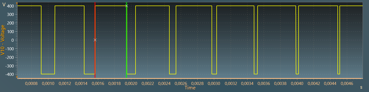
- For v_{ref} > v_c: upper switch is turned on (V_{10} = \frac{U_{dc}}{2})
- For v_{ref} < v_c: upper switch is turned off (V_{10} = -\frac{U_{dc}}{2})
The figures below show this principle:
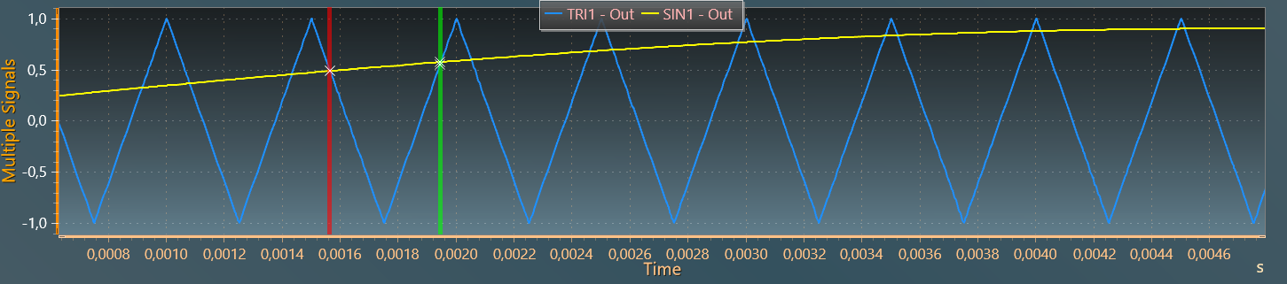
Here, the triangle carrier wave is between -1 and 1 (with a peak-to-peak amplitude of 2 and an offset of -1). The voltage reference must remain within these limits to keep a linear modulation. The modulation index is a the ratio between the peak of the reference voltage and the peak of the carrier voltage :
m = \dfrac{v_{ref}}{v_c}
This type of PWM technique is known as a carrier-based PWM approach because it uses a high-frequency carrier wave for voltage modulation. Since the reference is supplied as having the form of a sine wave, this carrier-based approach is specifically referred to as SPWM. Overall, the width of these pulses are modulated to obtain inverter output voltage control and to reduce the first harmonics at switching frequency (f_{sw}).
If the ratio between the carrier frequency (f_{sw}) and the reference voltage frequency (f_o) is high enough, the amplitude of the fundamental term of the output voltagewill vary linearly with the reference voltage and it can be written:
v_o = m \dfrac{U_{dc}}{2} sin(2\pi f_o t)
In this example, the control parameters of a PWM inverter to get a variable AC output voltage are then:
- modulation index: m = 0.9
- reference frequency: f_o = 50~Hz
Each leg has its own reference. References are phase-shifted by 120°.
The powerswitches are directly driven by the outputs of the control blocks: comparator and logic operator.
Simulation
AC voltages and currents
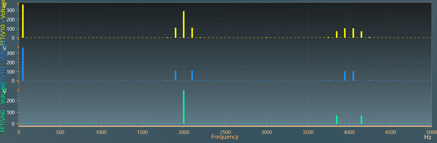
The figure below displays AC voltages V_{10},~V_{1N}~and~V_{N0}:
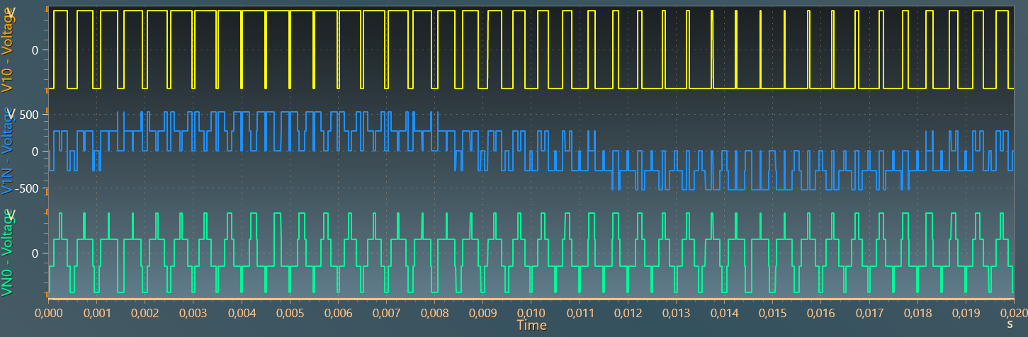
The frequency spectrum of these voltages is plotted below (with a base frequency of 50 Hz and 100 harmonics). The cancellation of the hompolar components from V_{10} to V_{1N} voltages can be clearly seen.
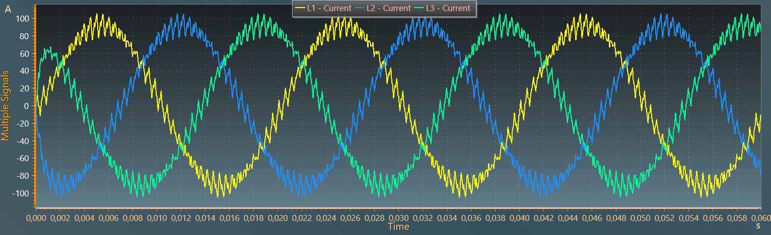
The figure below shows the AC inductor currents i_a, i_b, i_c and the creation of the 3-phase system.
Influence of the modulation index
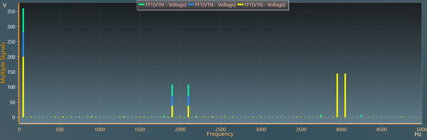
Finally, the figure below shows the evolution of the frequency spectrum of V_{1N} voltage for three modulation indices 0.5, 0.7 and 0.9. The linear dependence between the magntide of the fundamental term (V_{1N})_f and the modulation index can clearly be seen according to the relation:
(V_{1N})_f = m \times \dfrac{U_{dc}}{2}.
Reference
Pulse Width Modulation for Power Converters: Principles and Practice D. Grahame Holmes, Thomas A. Lipo