Getting Started with SIMBA
This tutorial explores the overall usage of "SIMBA software" and will cover the following topics:
- What is SIMBA software?
- How to download and launch SIMBA ?
- How to use the SIMBA Graphical User Interface?
- How to create a circuit ?
- How to set up the simulation settings?
- How to launch a simulation and observe the results?
What is SIMBA software?
✔ Step 1: Generic description
Simba is a modeling and simulation software for power electronics engineers. With an intuitive and sleek interface, it helps engineers to analyze and design complex systems such as power supplies, motor drives or grid-connected converters with unprecedented speed and simplicity.
✔ Step 2: Solver information
SIMBA proposes a new type of transient solver with a predictive time step which adapts to the different discontinuity events and time constants of the circuit. Thus, it offers an incredible performance and accuracy.
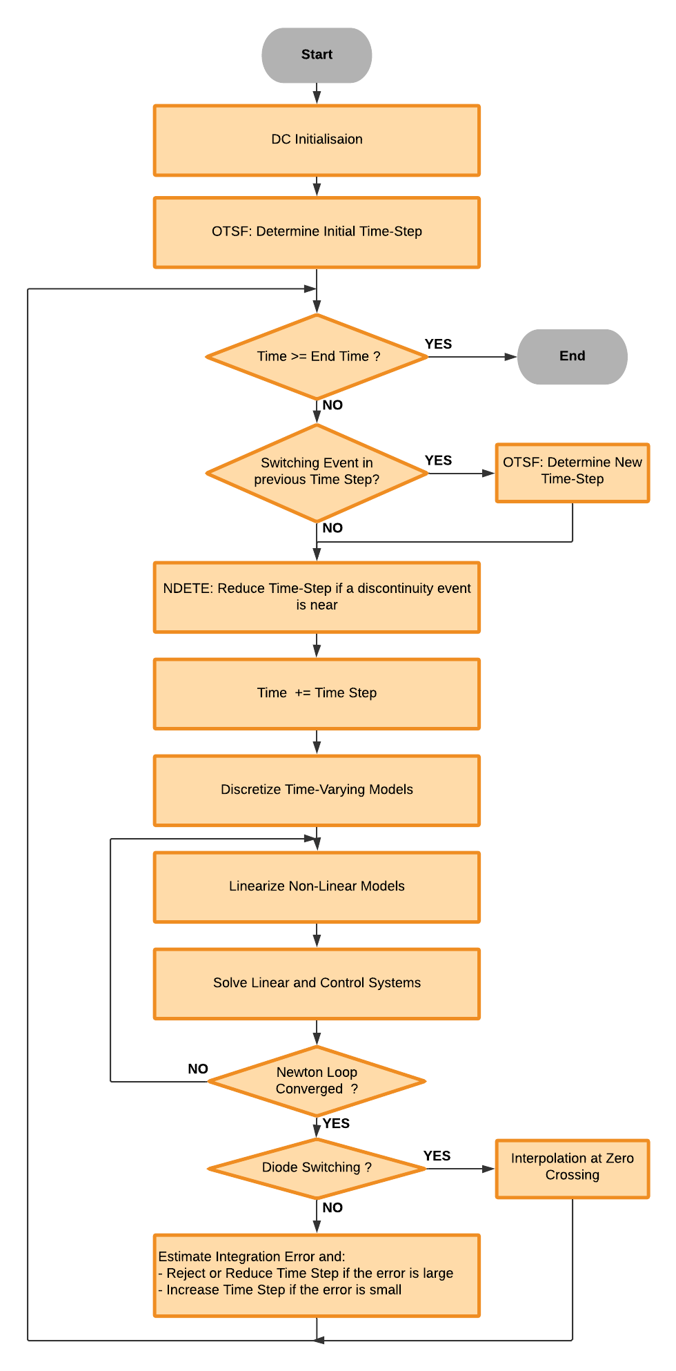
You'll find more details about SIMBA simulation engine in the “Simulation engine” section of the SIMBA documentation.
How to download and launch SIMBA ?
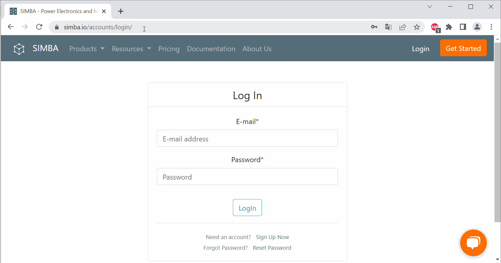
You have to go into official SIMBA website and create a user account via the login button.
Once connected to your account, you can go on 'download' tab on right side of the screen and click on 'SIMBA.exe'.
SIMBA is only available for Microsoft platform for now.
Once downloaded, simply run the executable file and few seconds later SIMBA will be opened.
A one-time activation process that requires an internet connection is required.
How to use the SIMBA Graphical User Interface?
SIMBA offers a sleek graphical user interface which does need any training so that users are immediately operational.
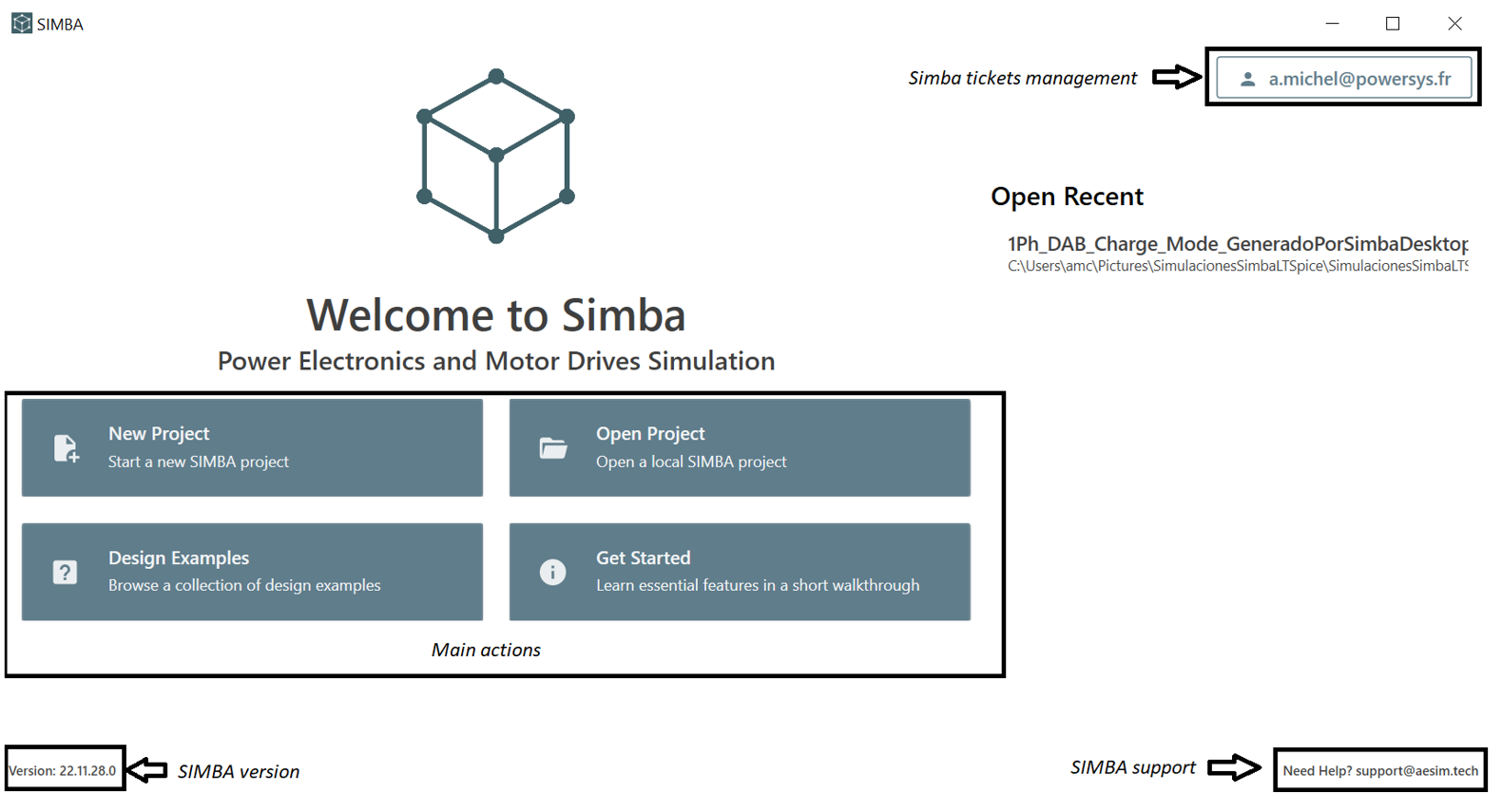
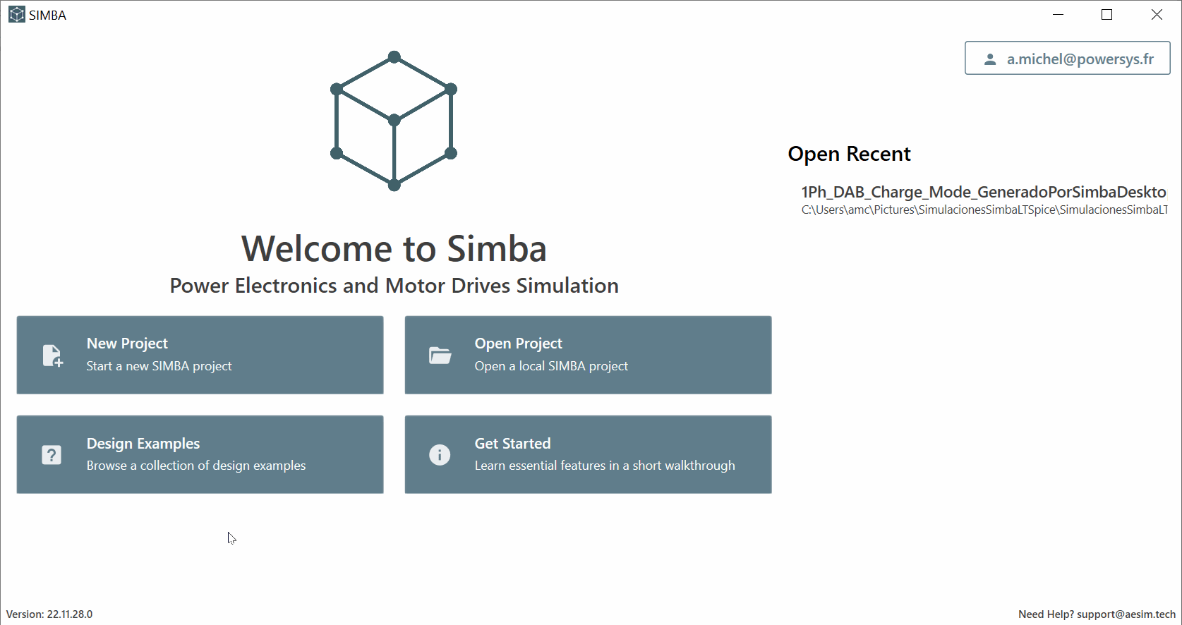
✔ Step 1: The "Welcome to SIMBA" page
This page contains the basics information in order to :
- Start a new SIMBA project (.jsimba file)
- Open an existing SIMBA project
- Open the collection of SIMBA Design examples
- Open the Getting Started Video for learning SIMBA essential features in few minutes
- Open the Recent SIMBA projects closed
- Give the SIMBA version which is used
- Provide the SIMBA support email address
- Manage SIMBA tickets created by the user + Exit & Deactivate SIMBA
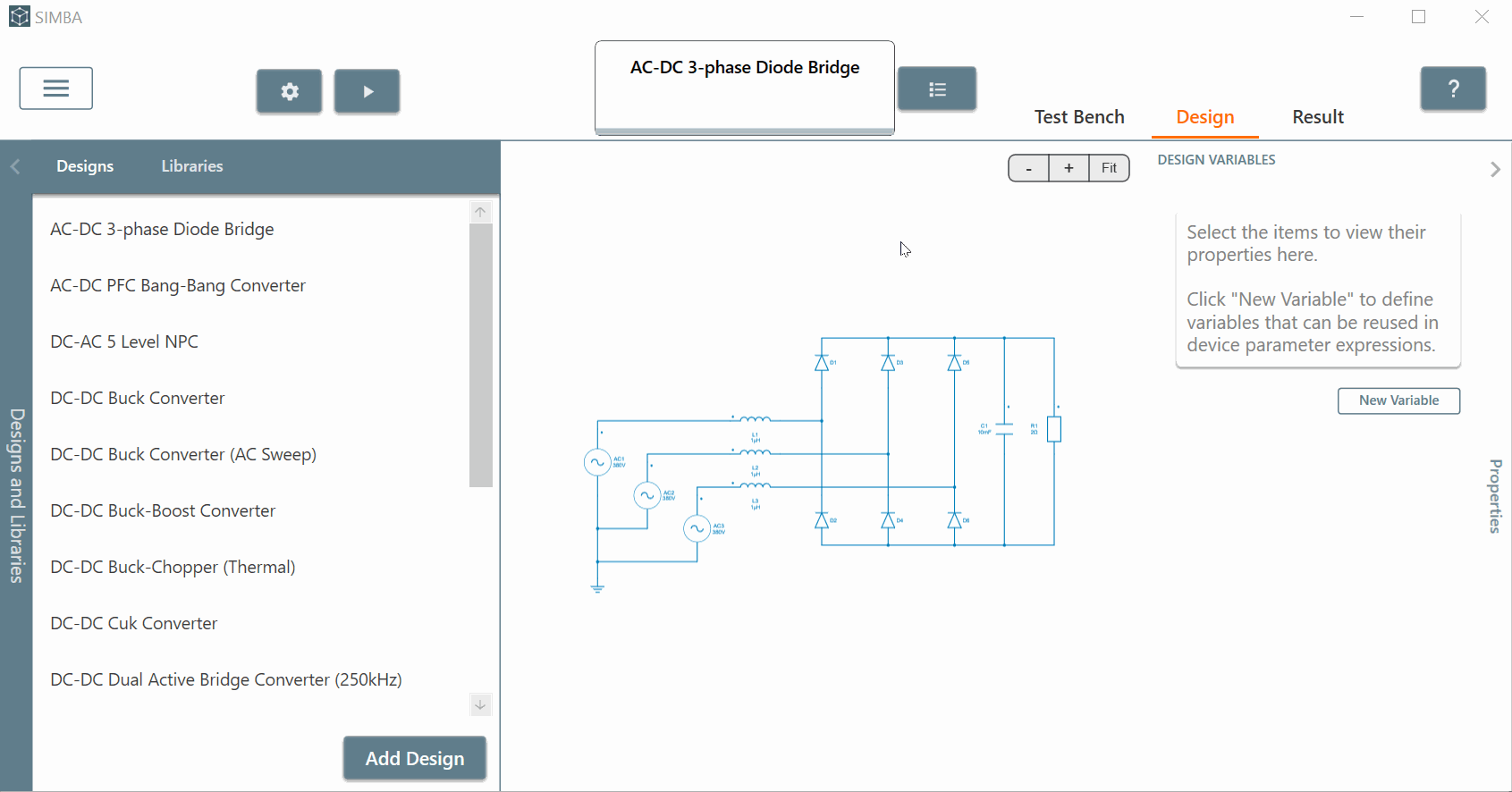
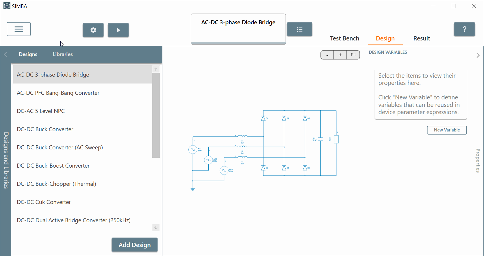
If you click on 'Design Examples' button, the main SIMBA interface window will be opened showing on the left side all the collection of examples created.
Those pre-built examples help the user to have a clear overview about SIMBA simulation capabilities.
✔ Step 2: Interface Overview
SIMBA adopts a common user interface and layout of a Design and Library explorer on the left, showing all the designs and models you have access to, a circuit editor in the center and a property panel on the right.
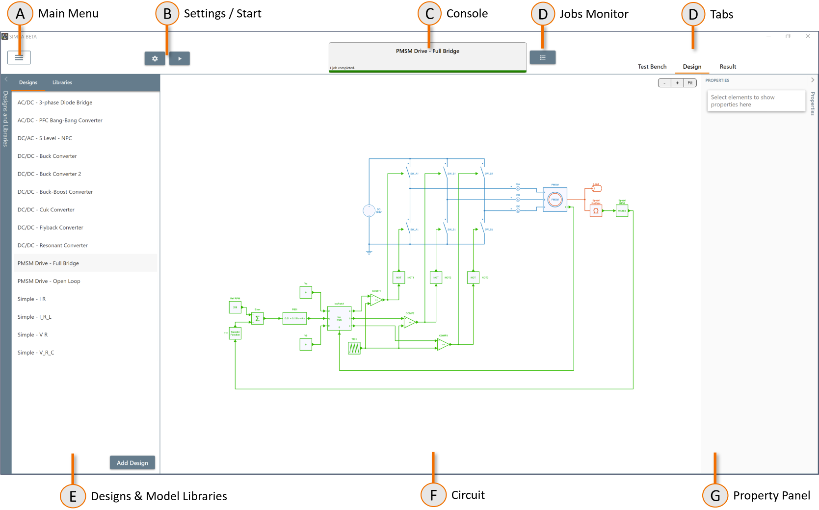
Moreover the interface of SIMBA is divided into three main tabs:
- Test Bench : allowing the user to set up 'parameter sweep' + 'ac sweep' analysis but also to add 'thermal data'.
- Design : allowing the user to design any power converter circuits. The design tab is the center of the modeling experience.
- Result : allowing the user to handle simulation results
More information can be found in the “Interface overview” section of the SIMBA documentation.
How to create a circuit ?
✔ Step 1: Project creation
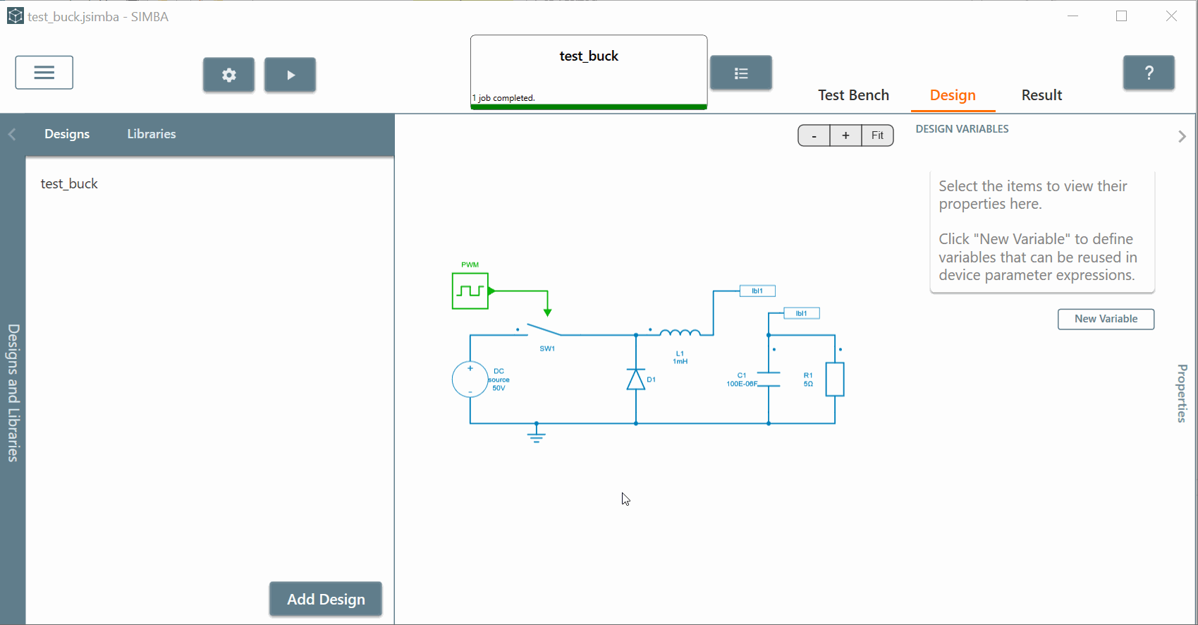
You have to go into SIMBA 'main menu', click on 'New Project' directly, a new SIMBA instance will be opened, save this project and give a name to this project: 'test_buck'.
Also rename the 'Design1' by 'buck'*.
In that sense we are going to simulate a simple buck converter.
✔ Step 2: SIMBA includes component libraries in different domains: electrical, mechanical, thermal and control. The electrical library includes components such as inductors, capacitors and power semiconductors switches, whereas the mechanical library includes electrical motors, inertia and friction element, etc.
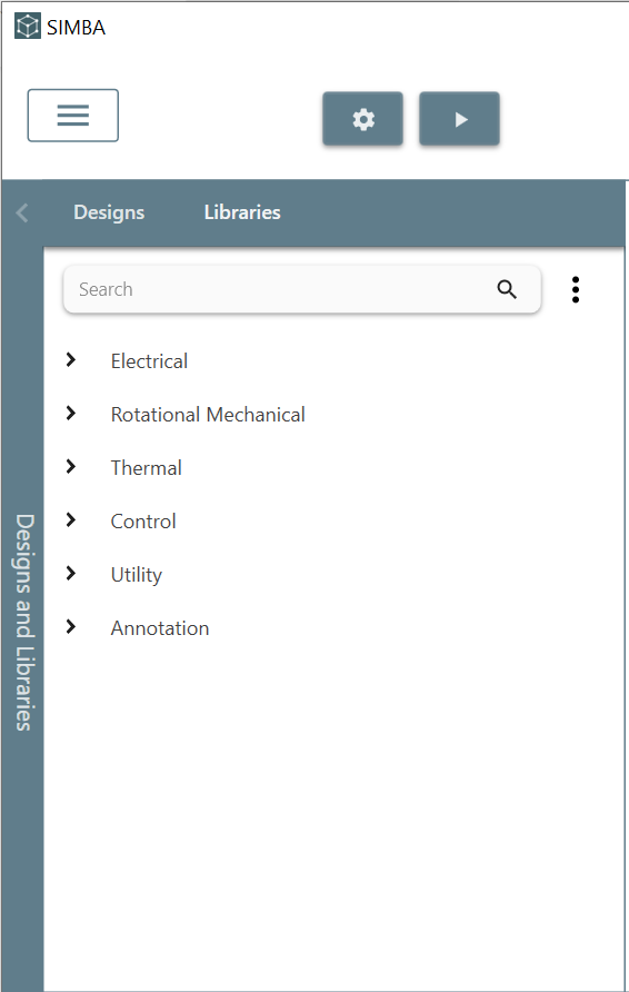
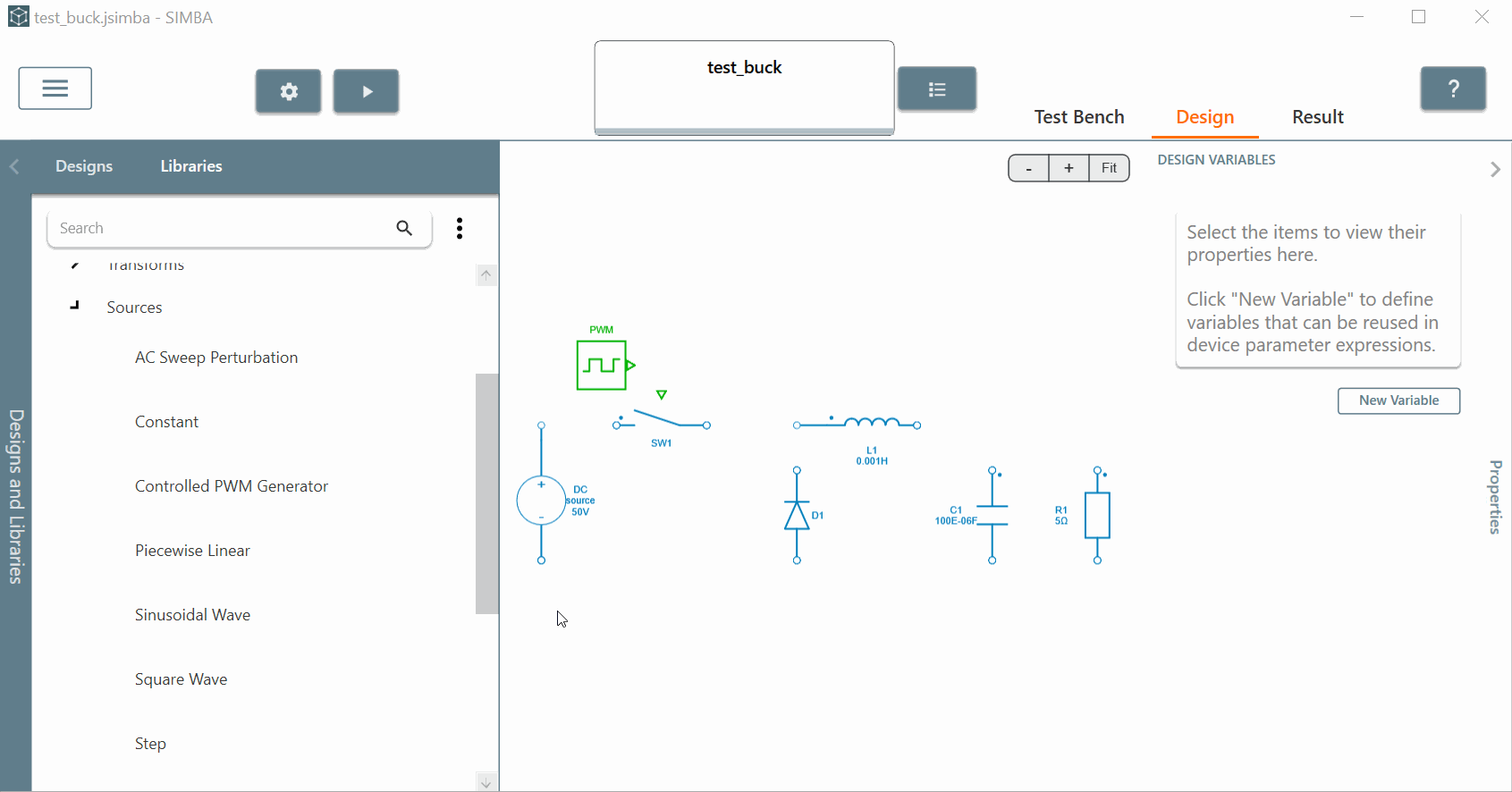
✔ Step 3: Let's search the needed components to design one buck converter.
- a 'DC Voltage Source' in 'Electrical' section, then 'sources'. Click on the '+' button and the source will be added to the main schematic. When a device is selected, rotation, flip, cut and copy options are available. As you can see, on the 'properties' panel on the right side, you can modify the voltage value, rename the DC source and select among the available scopes the variables to be saved during simulation. You can set the voltage to 50.
- a 'controlled switch' switch from 'Switches' section. To move a model, simply drag and drop it.
- a 'diode' from 'Semiconductors' section. Set as default the parameter values in the properties window.
- an 'inductor' from 'RLC' section. Don't change anything from properties window.
- a 'capacitor' and set the value of 100E-06 (or 100u as model parameters can use metric units and mathematical expressions as well). You can rotate this element on the schematic.
- a 'resistor' which here models the load. Set the value to 5 and check the boxes for 'voltage' and 'current' scopes. You can also rotate this component.
- finally add a 'square wave' block from 'Control' library and 'sources' section. Rename it such as 'PWM' and just modify the 'frequency' value to 5k. Check the box of the scope for this PWM block.
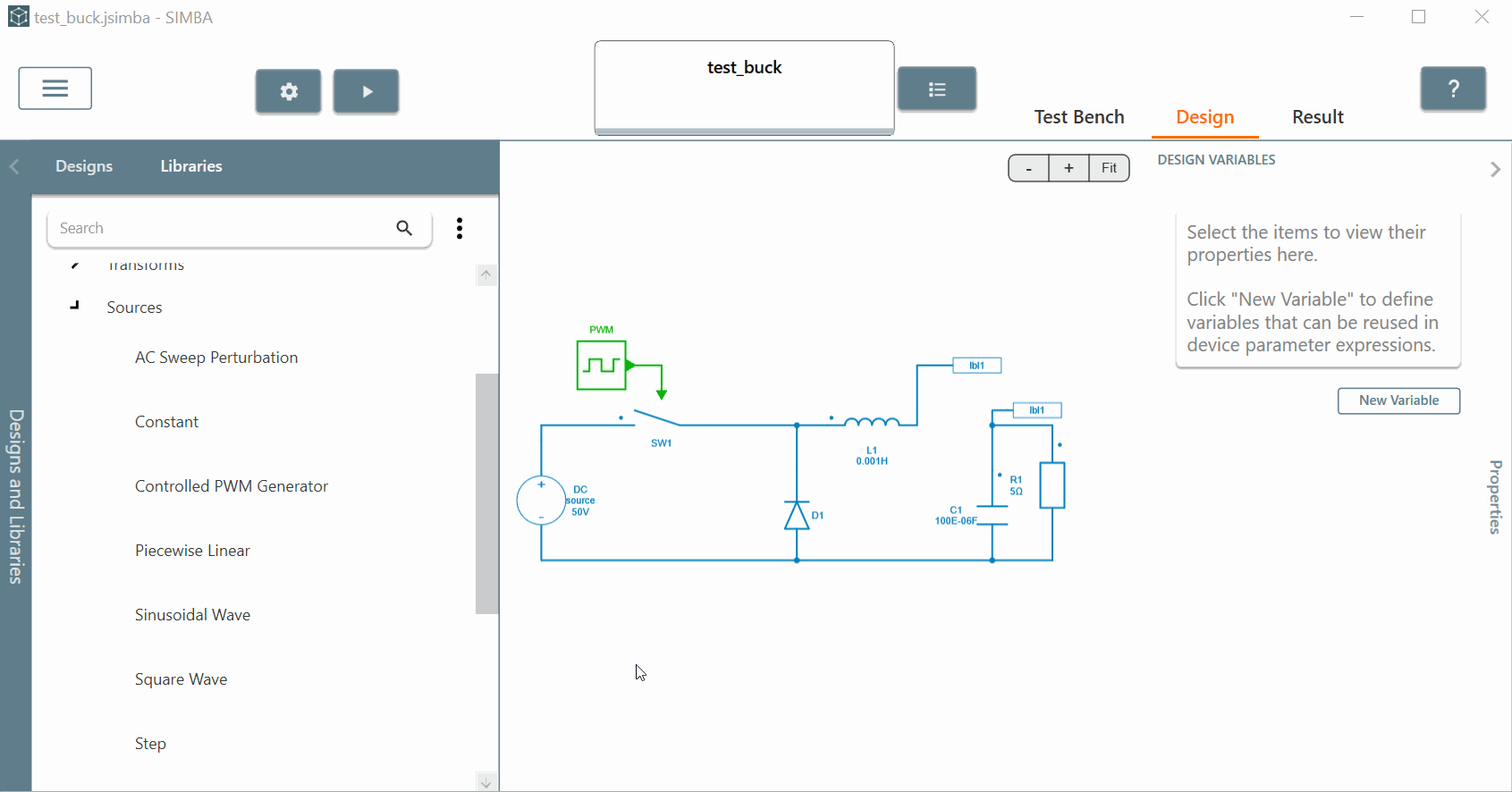
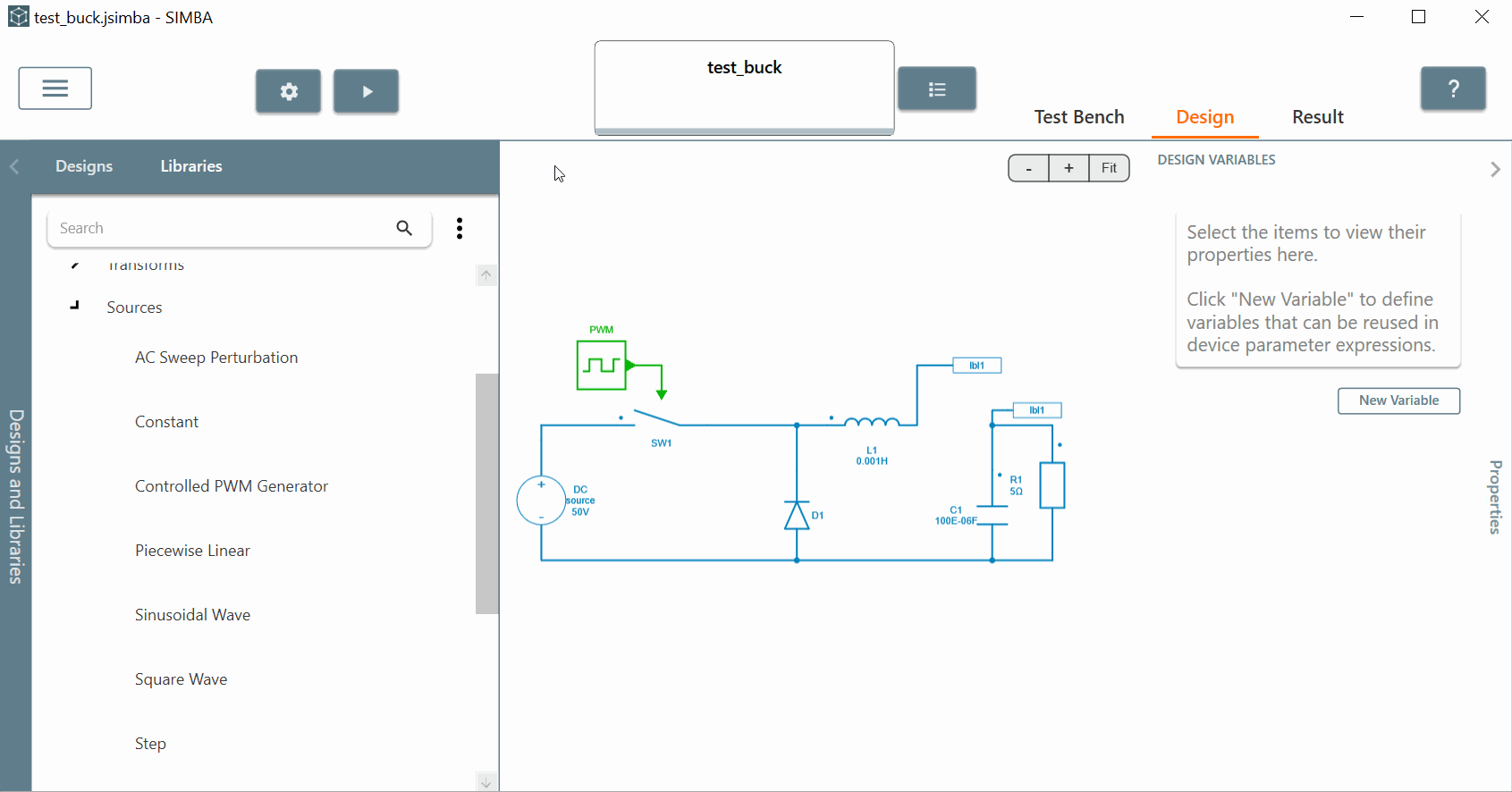
✔ Step 4: Now you can connect all those components together. You can click on the pin (circle) of the resistor and this action will create a connector (wire). Then click again on the pin of the capacitor and that will connect both together. You can also click on the 'connector' and click on '+' to add a new one. Then click into the 'inductor' pin and that will connect both again. You can repeat the process for all the components. Moving devices keep connections. Don't forget to connect your 'PWM' block to the 'control' pin of the 'switch'.
✔ Step 5: Labels can be used to connect different parts of a circuit without using connectors.
To add a label, simply select a connector and click on the Label button. In that sense we can create one label called 'lbl1' which will be used twice to link inductor and capacitor. Indeed the name needs to remain the same if you want to use the same connector.

How to set up the simulation settings?
When clicking on the wheel icon, two solvers are available: fixed time-step or predictive time step. For most of simulations, the predictive time step solver will offer a better compromise between speed and accuracy.
Let's set:
- solver type: predictive time step.
- min step: 1E-06 (the solver will adapt the time step during the simulation but this value will be the minimum taken into account).
- end time: 0.05 (this is the simulation end).
Note
It is also possible to select the simulation option: 'Stop at Steady State'. In this case, the solver will find itself the end time of the simulation and will stop it. More details can be found in the Simulation engine section of the SIMBA documentation.
How to launch a simulation and observe the results?
✔ Step 1: You can finally run the simulation by clicking on the 'play' button. You can see that the "job has failed" and the simulation didn't work with one error displayed. Just click on it and one message mentions that one ground needs to be connected to the system.
Let's find a ground into the 'libraries' tab by typing 'ground' into the search bar. Just add it into the schematic and connect it to the 'minus' sine of the DC voltage source.
Let's run again the circuit and the simulation should work without any errors anymore. As you can see, the job has been completed.
✔ Step 2: Results can be visualized in scopes during and after simulation by clicking into the 'Result' tab.
This tab allows the user to handle simulation results and analyze waveforms with different features:
- select simulation results to display different charts through the result list located on the left-hand side of the tab. Let's select here 'R1 - voltage'.
- manage different zoom options, display time cursors, extract measurement data, perform a Fast Fourier Transform (FFT) and export the chart with the toolbar located on the right-hand side of the tab.
You can add another waveform such as 'R1 - Current'. We can merge both curves and observe some measurements below such as 'Max, Min, Average, Peak to Peak'.
You can also filter the waveforms by typing the name of the signal needed. Let's type "R1" and you'll see all the signals related.
Finally the 'Split View' option available in the main menu splits the window showing simultaneously a design and its simulated waveforms which is really convenient.
This concludes this getting started video on SIMBA features.

Feel free to contact us if you have any questions and if you want to try SIMBA at contact@aesimtech.com.