Modeling a System in Electrical and Mechanical Domains
This tutorial explores the modeling and simulation of a system in electrical and mechanical domains.
This feature can help you to:
- simulate a complete motor drive
- connect an electrical circuit to a mechanical circuit
- feed back the value of the speed or torque to the controller.
How to connect different signals from the electrical, mechanical and control stage respectively?
To describe this functionality, we take the example of a full bridge power converter circuit and a PMSM drive. Here, we will observe how to connect each part in the same schematic.
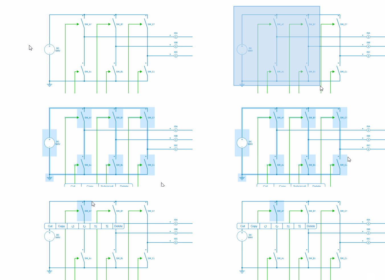
✔ Step 1: The power stage is a three-phase inverter with an ideal switch. We can observe the DC input voltage equal to 500 V and 6 switches drawing the legs of the power converter.
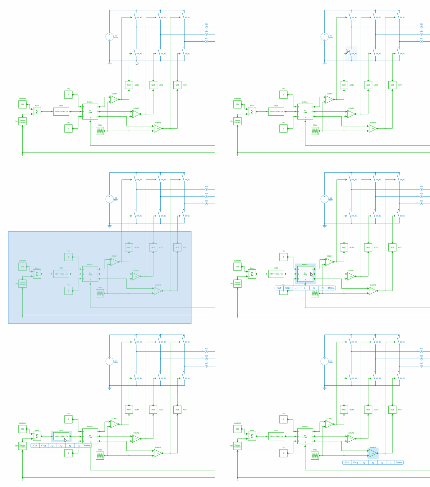
✔ Step 2 : Each switch is driven by green control signals. These signals come from a control stage that includes a 200RPM speed reference block, a PID controller, an inverse Park block and a PWM generation. In this circuit, we use a comparator block to create the gate signals.
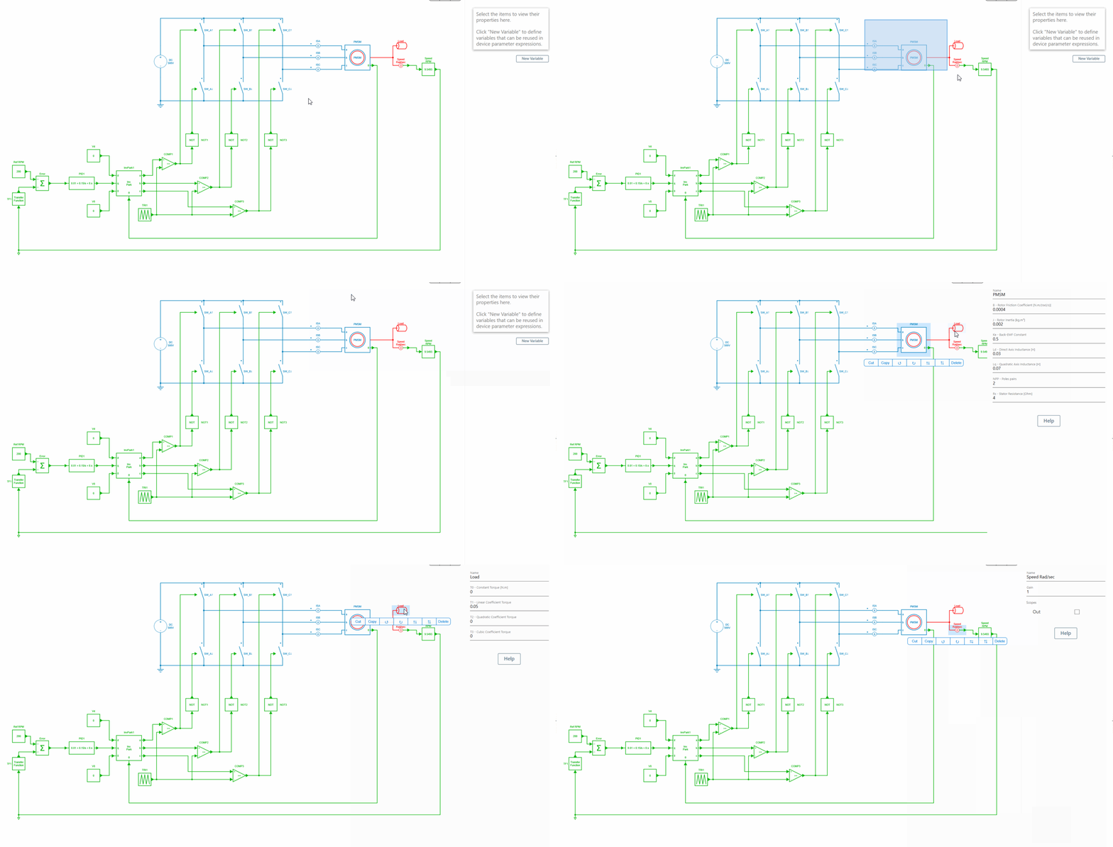
✔ Step 3 : Between the power stage and the control stage, the mechanical part has been implemented with a permanent magnet synchronous motor, a mechanical load and speed sensor blocks.
The 3 phase are directly connected to each phase a, b and c of the PMSM. The machine outputs give the electrical angular position (control signal) and a rotational mechanical pin modeling the shaft.
The electrical angular position pin can be directly connected to a control block and the shaft can be directly connected to a speed sensor and a mechanical load.
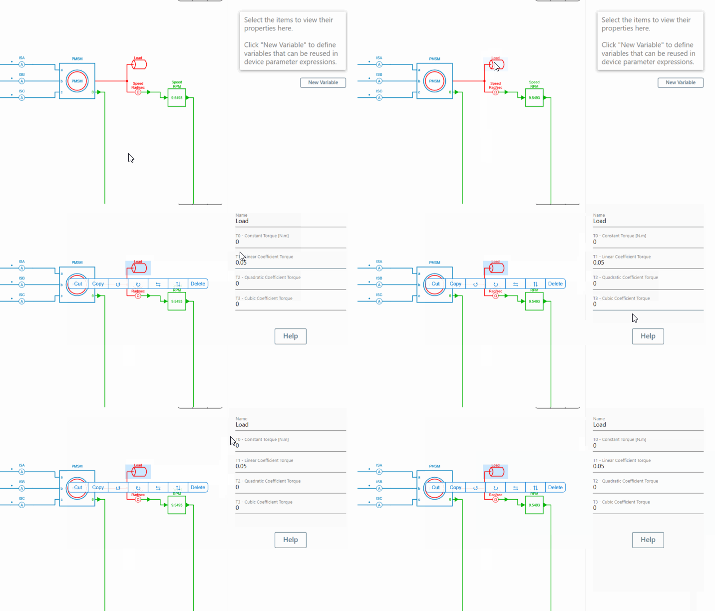
✔ Step 4: The mechanical load used in this example is a generic load and only the linear coefficient torque "T1" is configured with a value of 50m.
✔ Step 5: The output of the speed sensor also provides a control signal that can be sent directly to the control part without any interface blocks.
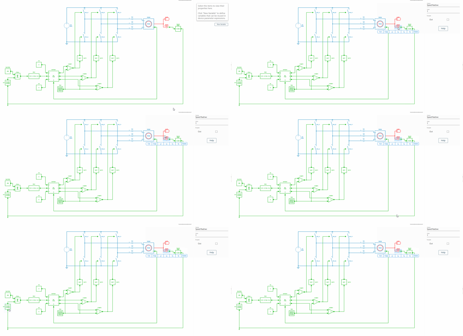
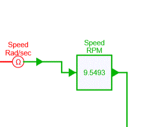
✔ Step 6 : A gain block has been added after the speed sensor block to calculate the speed in RPM.
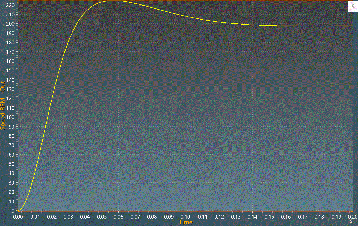
✔ Step 7 : Finally, after having executed the simulation, we can observe the results in the tab "Result" and check the "output speed". The speed reaches 200RPM as requested by the controller.
This concludes this tutorial on modeling a system in the electrical and mechanical domains. This feature shows you how to connect different types of domains.