Forward Converter
This example shows a DC-DC Forward Converter with:
- an input voltage of 325 V,
- an output voltage of 12 V,
- a power of 300 W transferred at the output resistor.
A Forward Converter is a DC-DC converter that uses a transformer to provide electrical isolation and can supply an output voltage that is either higher or lower than the input voltage. The output voltage is determined by the input voltage, the transformer turns ratio, and the duty cycle. Said converter is more complex than a flyback converter, but it can provide higher output power and energy efficiency. The secondary side of the forward converter functions similarly to a buck converter in terms of energy storage and delivery.
Model
To demonstrate the operation of a practical forward converter, a magnetizing inductance Lm was added in parallel to the primary winding of the TX1 transformer. The presence of this inductance results in voltage spikes occurring when the current is abruptly interrupted, which can lead to inefficient operation and potential damage to the converter. To address this issue, a tertiary (reset) winding is added to the transformer to provide a discharge path for the energy stored in the magnetizing inductance.
The picture below shows a circuit diagram of the forward converter (all components are ideal):
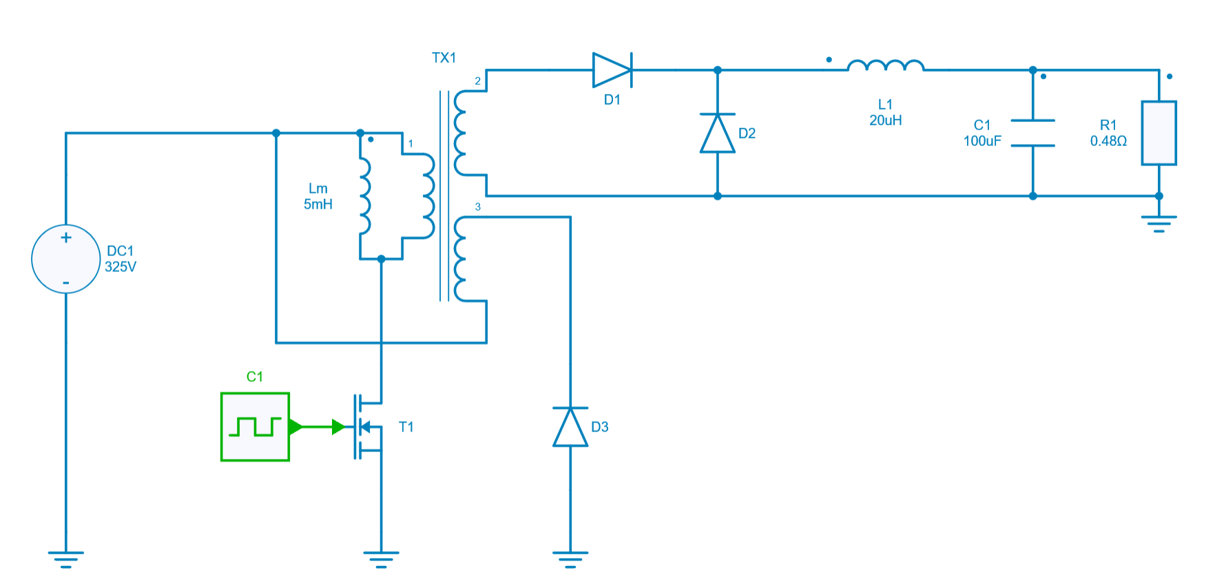
When the transistor T1 is closed (ON-state), the diode D1 is forward biased whereas diodes D2 and D3 are reverse biased. The primary winding of the transformer TX1 is energized from the DC1 voltage source. The current flowing through the magnetizing inductance Lm (magnetizing current) increases linearly, storing energy in the transformer core. At the same time, a voltage (scaled by a transformation ratio \frac{n_2}{n_1}) is induced in the secondary winding which is then rectified by a diode D1 and delivered through the LC low-pass filter to the output.
When the transistor T1 is opened (OFF-state), diodes D2 and D3 are forward biased whereas diode D1 is reverse biased. Consequently, the current is prevented from flowing in the primary and secondary windings of the TX1. Power is supplied to the load by the inductor L1 while the diode D2 provides a return path for the current. As transistor T1 is not conducting, the only return path for the magnetizing current is to flow through the tertiary winding of the transformer and diode D3. Thus the magnetizing current decreases linearly, and the core is gradually reset. The core resetting in a forward converter is necessary to prevent core saturation, which can occur due to residual magnetism. It also ensures that the transformer operates within its linear operating range, avoiding undesirable effects such as increased losses and reduced efficiency.
One more subinterval can be distinguished, namely, when magnetizing current reaches zero. Then the transistor T1, diode D1, and D3 are all reverse biased, while diode D2 is conducting.
Switch control
The switch model can be directly connected with a control signal. For this control, we use a PWM block with an amplitude of 1, a duty cycle of 0.4 and a frequency of 200 kHz.
Here are the values of the other components :
- inductor L1 : 20 µH and initial current = 0 A,
- inductor Lm: 5 mH and initial current = 0 A,
- capacitor C2: 100 µF and initial voltage = 0 V,
- resistor R1: 0.48 Ω,
- transistor T1: Ron = 0 Ω,
- diode D1: Rd = 0 Ω and Forward voltage = 0 V,
- diode D2: Rd = 0 Ω and Forward voltage = 0 V,
- diode D3: Rd = 0 Ω and Forward voltage = 0 V,
- transformer TX1: ratio \frac{V_2}{V_1} =\frac{6}{65}.
Simulation
All simulations were carried out with a duty cycle D=0.4
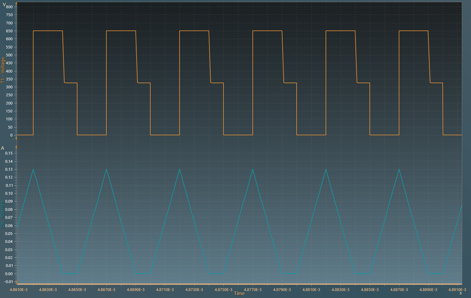
The results below present the transistor T1 voltage and current flowing through magnetizing inductance Lm:
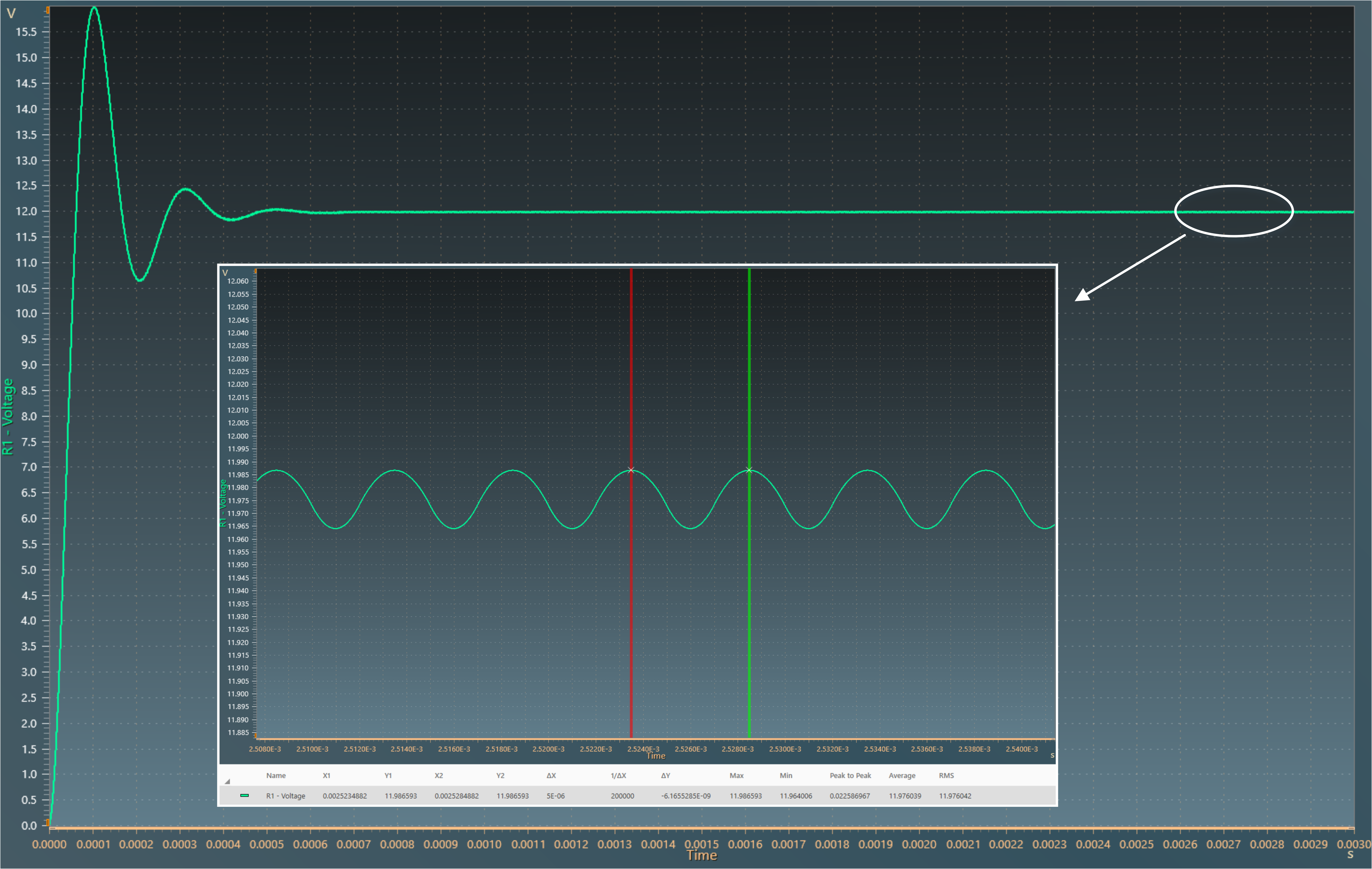
The results below show the output voltage across load resistor R1. A zoom shows a measure of the average value of this voltage: 12 V.
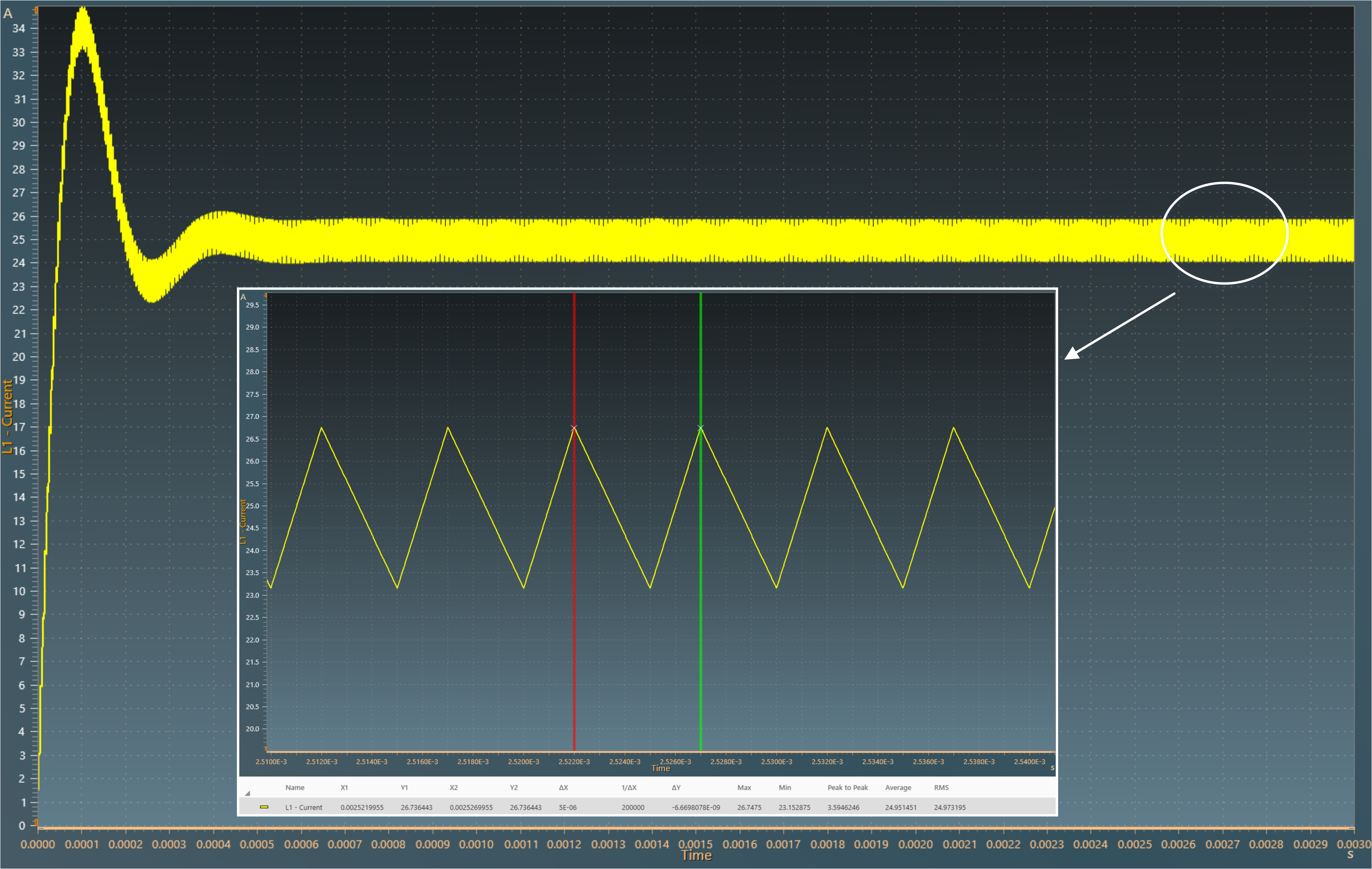
The results below show the current flowing through the inductor L1. A zoom shows a measure of the average value of this current : 25 A.
The obtained results follow the equation: V_{out} =\frac{N_2}{N_1} \times V_{in} \times D
with:
- {D}: Duty cycle
- V_{in}: Input voltage
- V_{out} : Output voltage
- N_2: Number of turns at secondary
- N_1: Number of turns at primary