Forward Converter with a multi-winding transformer modeled in magnetic domain
This example shows a DC-DC Forward Converter with a multi-winding transformer modeled in the magnetic domain of SIMBA. The main parameters are:
- an input voltage of 100 V,
- two output voltages of around respectively 12 V and 5V,
- output powers of respectively 100 W and 25 W.
This Forward Converter has four windings, two at the primary side (a classical topology where the second winding ensures the demagnetization of the transformer) and two at the secondary side to provide two output voltages.
Model
The figure below shows a circuit diagram of this forward converter:
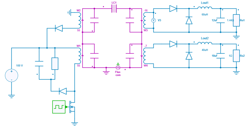
Except the transformer, all the components are ideal.
To get more details about the operation principle of a forward converter, the basic example can be a good start.
Switch control
A PWM block is used with an amplitude of 1, a duty cycle of 0.44 and a frequency of 100 kHz.
Transformer Model
The transformer modeled in the magnetic domain (see SIMBA documentation on magnetic modeling to get more details about this approach) uses:
- 4 winding-gyrator components with the following numbers of turns: N_1 = N_2 = 55, N_3 = 16, N_4 = 7,
- 1 linear core component LC_1 to model the magnetic core with a section A = 35 mm2, a magnetic path length l = 8 mm and a relative permeability \mu_r = 1500,
- 4 permeance components P_1 to P_4 of 2 nH each to model the leakage effects.
RCD clamp
The equivalent leakage inductor of the first winding leads to an overvoltage across the mosfet which should be limited. To achieve this, an RCD clamp circuit has been set.
Simulation
The results below present:
- the transistor T1 voltage (V),
- the flux rate (Wb / s),
- the common flux (Wb) through the magnetic core,
- the winding current (A),
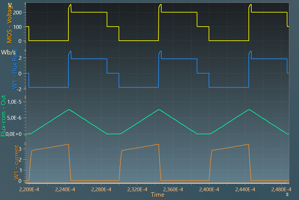
The effect of the leakage inductor can be clearly seen on the mosfet voltage when the current falls to 0.
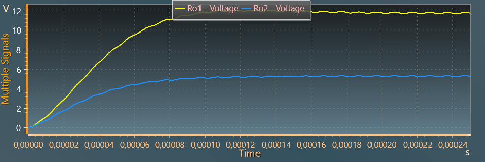
The results below show the output voltages across output resistor Ro1 and Ro2, with respective values slightly below 12 V and slightly above 5 V.
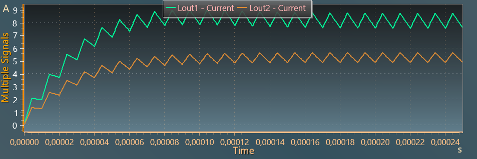
The last figure shows the ouput current through output inductors: