Using the Thermal Modeling of Power Switches
This tutorial explores the "Thermal modeling of power switches" feature of SIMBA.
This feature can help you to:
- carry out thermal modeling structure of a system,
- calculate conduction and switching losses,
- calculate component temperature,
- estimate efficiency of power converters,
- design cooling system such as heatsink.
How to use "Thermal modeling of power switches" capability for any circuits
To describe this feature, the example of the "DC-DC Buck-Chopper (Thermal)" circuit is considered.
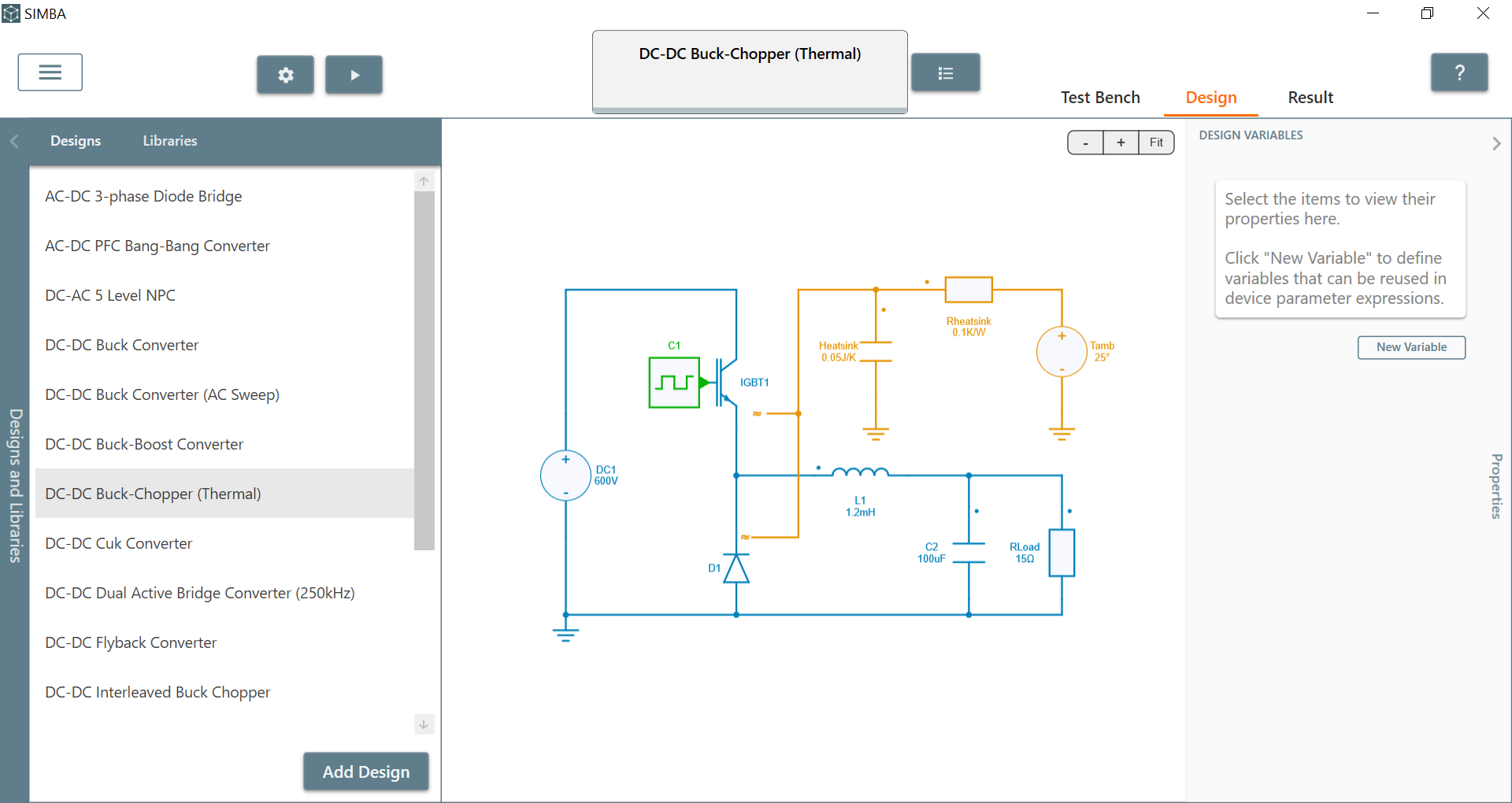
This schematic allows to:
- set up thermal modeling techniques,
- calculates both conduction and switching losses of one IGBT and one diode,
- determine junction temperature of both semiconductors,
- implement thermal RC network for the heatsink for determining its temperature.
✔ Step 1: First, let's observe the "thermal" library with 3 important items:
- sources,
- RC,
- probes.
For example, heatsinks can thus be modeled with networks of thermal resistors and capacitors.
The 'semiconductors' library is also really important because it gathers the major components such as 'diode', 'IGBT', and 'MOSFET' which can be associated with thermal data.
Those two combined libraries allow the user to implement its own thermal circuit in order to compute losses, temperatures and heat flows.
✔ Step 2: Secondly, let's check the Buck-Chopper power converter and more precisely the IGBT.
✔ Step 2.a: If you click on it you'll observe the on-resistance R_{on} and the forward voltage V_f which are equal to 0 for ideal behavior and which only affect electrical waveforms.
Check 'Thermal Data and 'Average loss calculation frequency' fields
These fields define:
- the thermal data used during the simulation to compute losses (i.e. heatflow) sent to the thermal model,
- the frequency value to compute the average values of switching, conduction and total losses which will be plotted in scopes.
✔ Step 2.b: In order to set up thermal data for losses and temperature purpose, you'll need to click on "Test Bench" tab and "Thermal Data" section. From there you can:
- import Thermal library file in .xml format that is currently supported by many semiconductors manufacturers. See tutorial on import thermal library xml file
- create your own thermal component by clicking on "new" button. You'll then be able to fill in all the data needed.
- modify and edit the actual thermal data provided.
✔ Step 2.c: For any new devices added to the list, you can observe some section to fill in:
-
Thermal impedance: you can decide between cauer of foster network for the junction to case thermal interface. You will need to specify the number of thermal resistors and capacitors representating the number of layers.
-
custom Tables and variables : you can create any new variables and even tables in order to use them later in formulas and get a more realistic losses behavior. The values of the custom variables are defined by the user in the device properties.
-
conduction loss: you'll need to fill in the data necessary for calculating conduction losses. You can decide between, lookup table, formulas and even both. You can add manually each data (temperature, number of points, the data of the lookup tables) or import them from a.csv file. The graph will be created and modified accordingly.
-
Turn-On and Turn Off loss: you'll need to fill in the data necessary for calculating turn on and off losses. You can decide between, lookup table, formulas and even both. You can add manually each data ( voltage and temperature, number of points, the data of the lookup tables) or import them from a.csv file. The graph will be created and modified accordingly.
Once a thermal data description has been created, it can be assigned to a power semiconductor switch (IGBT, MOSFET or diode) from schematic.
✔ Step 3: Thirdly, let's go back to the overall circuit. As you can see, when selecting thermal data for both IGBT and Diode in the "properties" window, an additionnal pin (orange) is added.
The conduction and switching losses of a power semiconductor must be collected and sent to a thermal circuit to determine the junction temperature of the power semiconductor.
This is achieved with this additional pin which allows the user to connect a power semiconductor to a thermal circuit (orange color) which can be a heat sink model, a thermal impedance or a temperature source.
Let's add 2 probes:
- a Temperature meter "V1": allowing to measure the Heatsink temperature
- a Heat flow meter "W1": allowing to measure the average total losses of both semiconductors = total heat flow.
✔ Step 4: Finally, let's click on "IGBT" component, select the 2 scopes: "average total losses" and "junction temperature".
Repeat the same process for the diode and run the circuit with original solver settings.
✔ Step 4.a: We can for example display the 'IGBT1 - Average total losses' and its 'junction temperature'.
We can conclude that :
- IGBT temperature increases a lot during the simulation and remain stable at the steady state.
- The average total losses are quite stable excepted at the beginning of the simulation.
✔ Step 4.b: We can display:
- 'V1 - Temperature' and 'Heatsink - Temperature' signals: they are equal and it is totally normal.
- 'W1 - Heat flow', 'D1 - Average total losses (W)', and 'IGBT1 - Average total losses (W)' : you can clearly observe that Heat flow W1 is equal to the addition of both average losses as mentionned in step 3.
All those results are computed thanks to the thermal data entered by the user.
More information about "Thermal Losses" calculation could be found in the Thermal analysis section of Simba documentation.
This concludes this tutorial video about the "Thermal modeling of power switches" feature of SIMBA.