AC sweep examples
The examples show the validation of AC sweep analysis with analytical equations derived from the book Transfer Functions of Switching Converters by Christophe P. Basso.
These examples deal with a buck converter, a boost converter and a flyback converter.
Below are presented the details and results of the buck converter in current continuous mode (CCM) and in discontinuous mode (DCM) with open loop transfer functions of:
- control to output voltage,
- input voltage to output voltage.
Buck converter model
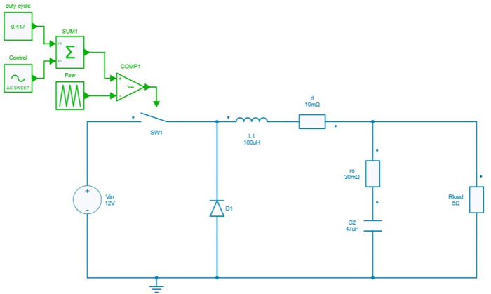
Below provided figure shows the method adopted to perform AC sweep for Buck Converter in CCM mode of operation.
CCM Transfer functions
Control to output voltage
The theoretical analytical equation in continuous current mode (CCM) is:
Where the s domain can be converted to digital domain by replacing s = j\omega.
To get this transfer function with SIMBA, the design of the buck converter is loaded and associated with a sweep test bench.
design = project.GetDesignByName('Buck Converter - CCM - Open Loop');
acsweep =  project.GetACSweepByName('AC Sweep - Buck CCM - Open Loop');
acsweep.Design = design;
Frequency range is then defined as well as the magnitude of the perturbation along the frequency range.
acsweep.Fmin = Fsw/1000;
acsweep.Fmax = Fsw/10;
acsweep.MagMin  = 0.03;
acsweep.MagMax  = 0.05;
acsweep.NumberOfPoints  = 31;
job = acsweep.NewJob();
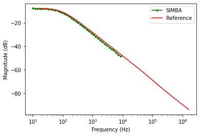
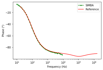
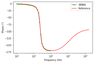
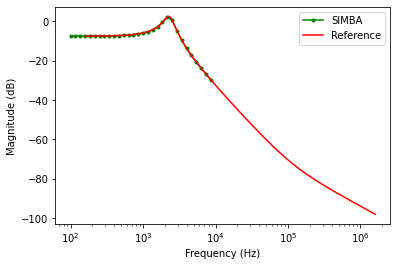
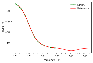
The figure presented below shows the results for the comparison between the theoritical reference and SIMBA in terms of the magnitude and phase plot for control to output voltage.
Input voltage to output voltage
The theoretical analytical equation in continuous current mode (CCM) is:
To get this transfer function with SIMBA, the design of the buck converter is loaded and associated with a sweep test bench.
design = project.GetDesignByName('Buck Converter - CCM - Open Loop');
acsweep =  project.GetACSweepByName('AC Sweep - Buck CCM - Input To Output');
acsweep.Design = design;
As for the previous analysis, frequency range is then defined as well as the magnitude of the perturbation along the frequency range.
acsweep.Fmin = Fsw/1000;
acsweep.Fmax = Fsw/10;
acsweep.BaseSwitchingFrequency = Fsw;
acsweep.BaseSwitchingFrequencyEnabled = False;
acsweep.MagMin  = 0.5;
acsweep.MagMax  = 0.5;
acsweep.NumberOfPoints  = 31;
job = acsweep.NewJob();
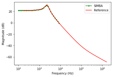
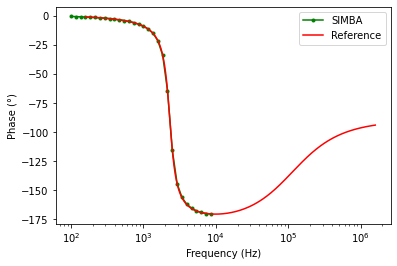
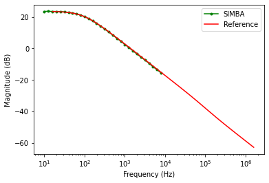
The figure presented below shows the results for the comparsion between the theoritical reference and SIMBA in terms of the magnitude and phase plot for input to output voltage.
DCM Transfer functions
Control to output voltage
The theoretical analytical equation in discontinuous current mode (DCM) is:
This expression can further be simplified as:
where \Delta = s^2+s(4V_{c}L+RV_{in}D^{2}T_s)
To get this transfer function with SIMBA, the design of the buck converter is loaded and associated with a sweep test bench.
design = project.GetDesignByName('Buck Converter - DCM - Open Loop')
acsweep =  project.GetACSweepByName('AC Sweep - Buck DCM - Open Loop');
acsweep.Design = design;
acsweep.Design = design;
acsweep.Fmin = Fsw/10000;
acsweep.Fmax = Fsw/10;
acsweep.MagMin  = 0.05;
acsweep.MagMax  = 0.1;
acsweep.NumberOfPoints  = 31;
job = acsweep.NewJob();
Input voltage to output voltage
The final expression for input to output is expressed as:
To get this transfer function with SIMBA, the design of the buck converter is loaded and associated with a sweep test bench.
design = project.GetDesignByName('Buck Converter - DCM - Open Loop')
acsweep =  project.GetACSweepByName('AC Sweep - Buck DCM - Input To Output');
acsweep.Design = design;
acsweep.Fmin = Fsw/10000;
acsweep.Fmax = Fsw/10;
acsweep.MagMin  = 5;
acsweep.MagMax  = 10;
acsweep.NumberOfPoints  = 41;
job = acsweep.NewJob();
status = job.Run();
The figure presented below shows the results for the comparsion between the theoritical reference and SIMBA in terms of the magnitude and phase plot for input to output voltage.