Inductor (Coupled)
Description
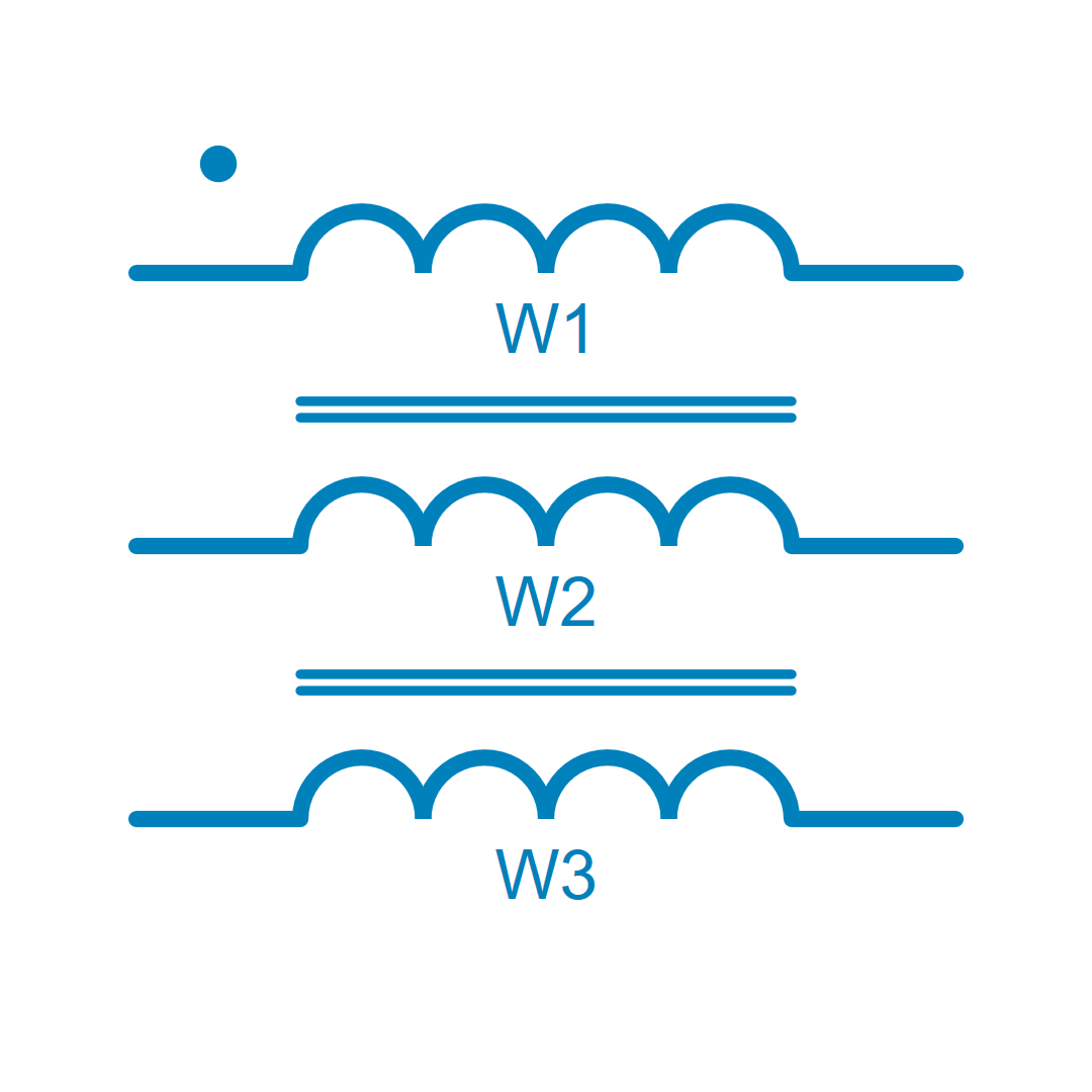
This component provides two or more mutually coupled inductors. For two or three coupled inductors, it is electrically equivalent with a non-ideal transfomer (see details in section below).
The size n of the matrix corresponds to the number of windings. L_i is the self inductance of the internal inductor and M_{i,j} is the mutual inductance (see below).

The inductance matrix should not be singular in order to be invertible. In case of ideally coupled inductors, the inductance matrix can become singular and an ideal transformer component should be preferred to model these ones. The mutual inductances M_{ i,j} can also be linked with a coupling factor K_{i,j} such as: M_{ i,j} = k_{ i,j} \sqrt{ L_i L_j}.
Case of two coupled inductors
The electric model of two coupled inductors is equivalent to a non-ideal transformer model:
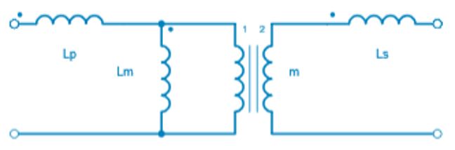
L_m: the magnetizing inductance at the primary side,
L_p: the leakage inductance at the primary side,
L_s: the leakage inductance at the secondary side,
m: the transformer ratio.
The electric model of two inductors and its parameters are then:
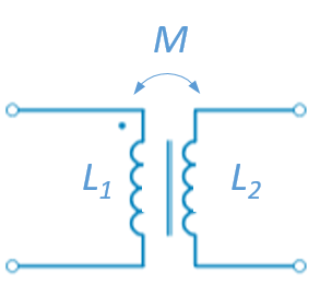
L_m = \frac{M}{m}
L_p = L_1 - \frac{M}{m}
L_s = L_2 - m.M
Case of three coupled inductors
The electric model of three coupled inductors is also equivalent to a non-ideal transformer model:
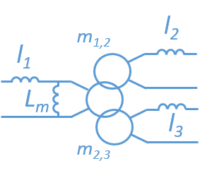
L_m = \frac{M_{ 13} M_{ 12}}{ M_{23}}
l_1 = L_1 - \frac{M_{13} M_{12}}{M_{23}}
l_2 = L_2 - \frac{M_{23} M_{12}}{M_{13}}
l_3 = L_3 - \frac{M_{23} M_{13}}{M_{12}}
Library
Electrical > RLC
Pins
| Name | Description |
|---|---|
Parameters
| Name | Description |
|---|---|
| NumberOfWindings | The number of ideal inductors. |
| Inductance | The inductance matrix (H). In order to model a magnetic coupling between the windings, a square matrix must be entered. |
| Iinit | Vector of Initial inductor currents (A). The vector size must be equal to the number of windings. |