Induction machine drive example with a V / f scalar control
This example shows a induction machine supplied with a PWM inverter and driven with a V / f scalar control, with:
- a dc bus voltage of 600 V,
- a switching frequency of 10 kHz,
- a variable load torque with a square-law characteristic (such as booster pumps and centrifugal fans), with T_{load} = 0.1 + 0.003 \times \Omega^2.
Control structure
The diagram below shows the closed-loop V / f control structure.

This V / f control makes possible to drive the induction machine with a constant flux (considering the stator resistance can be neglected).
Principle of the control
The electromagnetical torque of an induction machine can be given by:
The maximum torque - when \omega_r = R_r / L_r - is then:
- N_{pp} number of pole pairs
- V_s equivalent single-phase voltage
- \omega_s pulsation of the stator currents
- \omega_r pulsation of the rotor currents
- R_r rotor resistance at the stator side
- L_r rotor leakage inductor at the stator side
If the ratio V_s / \omega_s can be kept constant, the maximum value of the torque will be constant for different synchronous speeds \Omega_s. This principle is illustrated in the figure below:
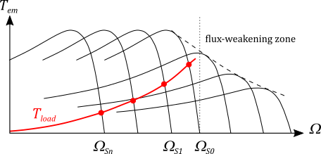
For low speeds, the ohmic voltage drop due to the stator resistance cannot be neglected. For high speeds, when the voltage reaches this maximum, this ratio decreases leading to a flux-weakening zone and a decreasing of the torque. This makes possible to reach higher speeds than the nominal speed.
Industrial variable speed drives propose modified V / f control profiles with:
- an adding term for low frequencies to keep a minimum torque,
- a saturation when the voltage reaches its maximum value.
This control profile is illustrated in the global control diagram above in the V / f block. Such a control profile has not been implemented in the demo example as it was not necessary.
Torque control
The torque can then be controlled with \omega_r according to the first expression of the electromagnetical torque. For small values of \omega_r, the torque expression can even be considered linear with \omega_r:
Speed loop
The speed loop involves a classic PI regulator.
Reference
This circuit example is issued from an example proposed by Christophe Haouy.