Saturable Inductor

Description
A saturable inductor with magnetic core saturation.
This component represents a nonlinear inductance using piecewise linear approximation. In this device, inductance C defined in the property view is an apparent inductance. The apparent inductance L is defined as the ratio of magnetic flux linkage \phi to the current I through the inductor: L = \frac {\phi}{I}
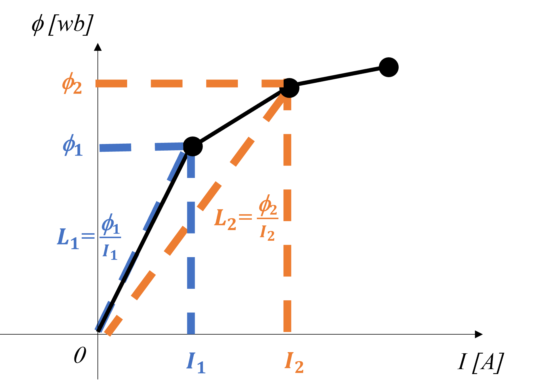
When the circuit is simulated, SIMBA solver converts this apparent inductance into a differential inductance L_{diff}, which is defined as the ratio of the rate of change of flux linkage \phi to the rate of change of the current I. For instance, the differential inductance between I_1 and I_2 is L_{diff} = \frac {\phi_2 - \phi_1}{I_2 - I_1}
Saturation is expressed by segmented data points, such as (I1, L1), (I2, L2), (I3, L3), ..., with current values I ≥ 0. For negative current, mirror inductance values are used. When the input current falls outside the range of data points, the first or last inductance value is used. For input current between segmented points, the next point is used so that the flux value calculated from the inductance is linearly interpolated.
SIMBA returns an error if:
- Input data points are not in ascending current order.
- Calculated flux linkages \phi don't monotonically increase with current.
- Negative current values are included in segmented data points.
Library
Electrical > RLC
Pins
| Name | Description |
|---|---|
| P | Positive Pin (●) |
| N | Negative Pin |
Parameters
| Name | Description |
|---|---|
| ApparentInductance | Current(A)-Inductance(H) Matrix |
| Iinit | Inductor current, in A |