SIMBA 2021.10
Welcome to SIMBA 2021.10! This major release brings major changes including improved solver, AC Sweep and the new Stop at Steady State option.
If you haven’t yet, be sure to download it.
Improved Solver
The solver is now about 10x more accurate with even faster simulation.
The maximum relative tolerance of the integration error is now set to 10E-7 instead of 10E-6 previously and this computational overhead is more than compensated by improvements and optimizations of the solver engine.
AC Sweep
A new test bench is available: AC Sweep. It uses the steady-state algorithm to calculate the transfer function of a periodic system at different user-defined frequencies. More information here.

Stop At Steady-State
When Stop at Steady-State is enabled, the End Time parameter is not used, and the simulation stops when SIMBA detects the steady state.
This feature is particularly useful during a parametric analysis because each run can have different time constants and the Stop at Steady-State feature ensures that each run will stop at its steady state. To determine if the steady state is reached, SIMBA analyzes the RMS value and the highest non-DC harmonics (if any) of all simulated state variables.

Library Explorer
A new search option is added to the Library tab to quickly search and find your models.

New PWM Generator and Switch with Threshold models
Two new models are added to the library:
New Dual Active Bridge Example
This example shows a Dual Active Bridge converter with:
- an input voltage of 95 V,
- an output voltage of 380 V,
- an output power of 1 kW.
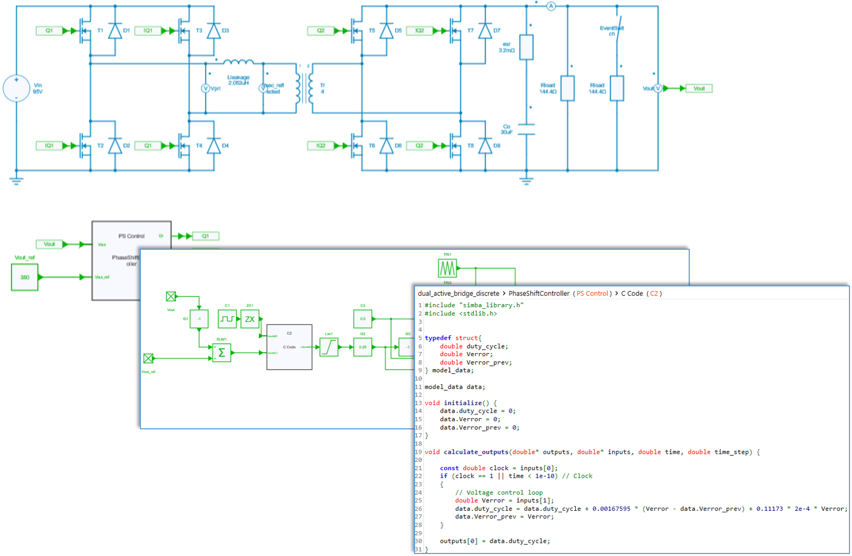
PWM control
Each bridge with a duty cycle of 50%. The phase-shift between the two bridges is set by the discrete controller (PI regulator) in order to regulate the output voltage.
Power semiconductor switches
Mosfets of this example are set with conduction parameters: a first R{on} resistance for the channel conduction mechanism (forward and reverse conduction when the transistor's gate id driven high) and a second R_{on} resistance and a V_f drop voltage for the body diode.
Note : with the command used in this example, mosfets are always used in synchronous rectification mode which means that the controlled conduction mechanism (channel) is the major contributor for conducting the reverse current compared to the body diode conduction.
Transformer ratio
The transformer ratio can be chosen according required values of primary and secondary voltages. Here a secondary voltage of 380V is required and a primary voltage of 95V is considered to be the lowest possible value (worst case), which leads to a transformer ratio of 4.
Inductor design
The expression below gives the maximum power which can be transferred for a phase-shift angle of \pi / 2 [1]:
with m = \frac{V_2}{V_1}, the transformer ratio.
A maximum power of 2 kW and a margin of 10 % si considered. At a switching frequency of 250 kHz, with V_1 = 95V and V_2 = 380V, this leads to a maximun inductor value of 2.051 \mu H.
This value is compatible with typical values of leakage inductors of high-frequency transformers with these levels of power, voltages and ratio.
[1] M. Blanc, Y. Lembeye, J.P. Ferrieux, Dual Active Bridge (DAB) pour la conversion continu-continu, Techniques de l'ingénieur E3975, 2019.
Quality of life
In 2021.10, several bugs are corrected and the general stability of SIMBA is improved. The complete list of changes is available here.
Roadmap
If you are interested, you can check our roadmap and a public GitHub project is available to share ideas, report bugs, and suggest new features.