Public Beta 4 (2020.10.26)
Welcome to the Public Beta 4 of SIMBA. There are a few updates that we hope you will like. If you haven’t yet, be sure to download it. The complete list of changes is available here.
Python API
We are excited to announce that the SIMBA Python API, aesim.simba is ready and is available on PyPi here.
One of the first design goals, when we started the development of SIMBA was to provide the greatest scripting experience. Scripting is essential since automating calculations is required in almost all workflows including:
- Statistical studies: Parametric, Monte Carlo, Pareto...
- Fault analysis
- Export of simulation results
We decided very early to support Python:
- it offers a good balance between simplicity and functionality;
- it has a strong community support: state-of-the-art free and open-source libraries are available for almost everything a power electronic engineer will ever need in terms of scripting including signal processing libraries, plot librarities, and statistical libraries;
- it can be used in an interpreter shell or through a Jupyter Notebook.
To get started, check our overview page and our get-started examples hereunder or here.
1 2 3 4 5 6 7 8 9 10 11 12 13 | |
1 2 3 4 5 6 7 8 9 10 11 12 13 14 15 16 17 18 19 20 21 22 23 24 25 26 27 28 | |
1 2 3 4 5 6 7 8 9 10 11 12 13 14 15 16 17 18 19 20 21 22 23 24 25 26 27 28 29 30 31 32 33 34 35 36 37 38 39 40 41 42 43 44 45 46 47 48 | |
Note
We are often asked if SIMBA is written in Python and the answer is no. SIMBA is primarily developed in modern C++ (Solver) and C# (Graphical User Interface) for performance reasons. The Python codebase of SIMBA is extremely small and serves as the interface with our main code.
Semiconductor models improved
Diode, IGBT, and MOSFET ideal models are improved with additional parameters to consider threshold voltage and on-resistance.
Results
Undo
A new option to Undo the last zoom action is available in the toolbar:
Sync charts zoom and cursors.
When multiple charts are displayed, a new option to synchronize the zoom and cursor actions of all charts is available in the toolbar:
New Examples
Two new examples are added in Beta 4.
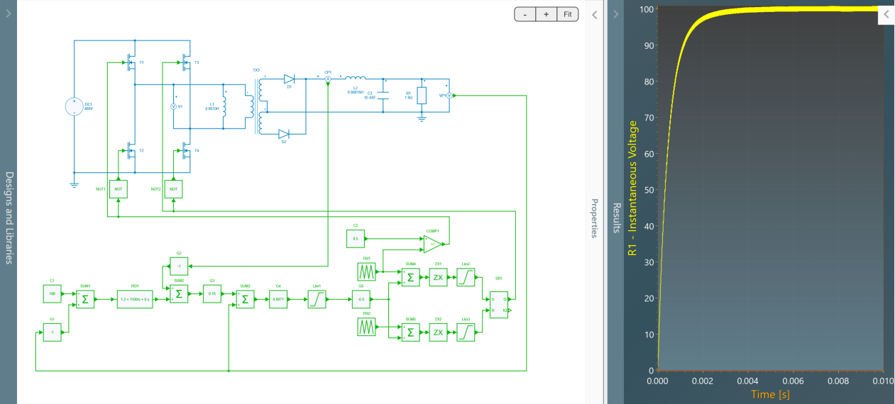
DC/DC Phase Shift Full Bridge
This example shows a Phase-Shift Full Bridge converter with:
- an input voltage of 400 V,
- an output voltage of 100 V,
- a power of 53 kW.
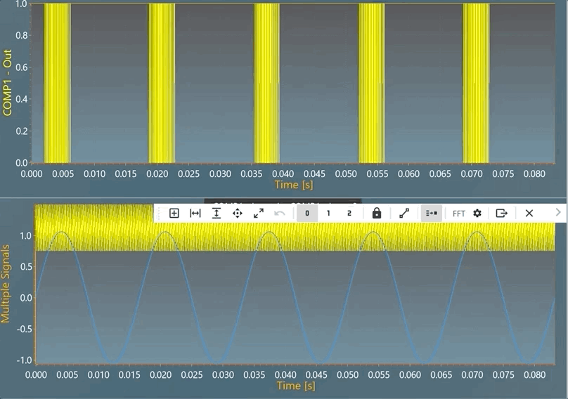
Phase-shift PWM
Each switching cell is driven with a duty cycle of 50%. The control signal of the phase-shifted switching cell is created from the duty cycle reference according to the figure below. The principle is to compare the duty cycle reference with a sawtooth to determine the phase-shift between the two legs.
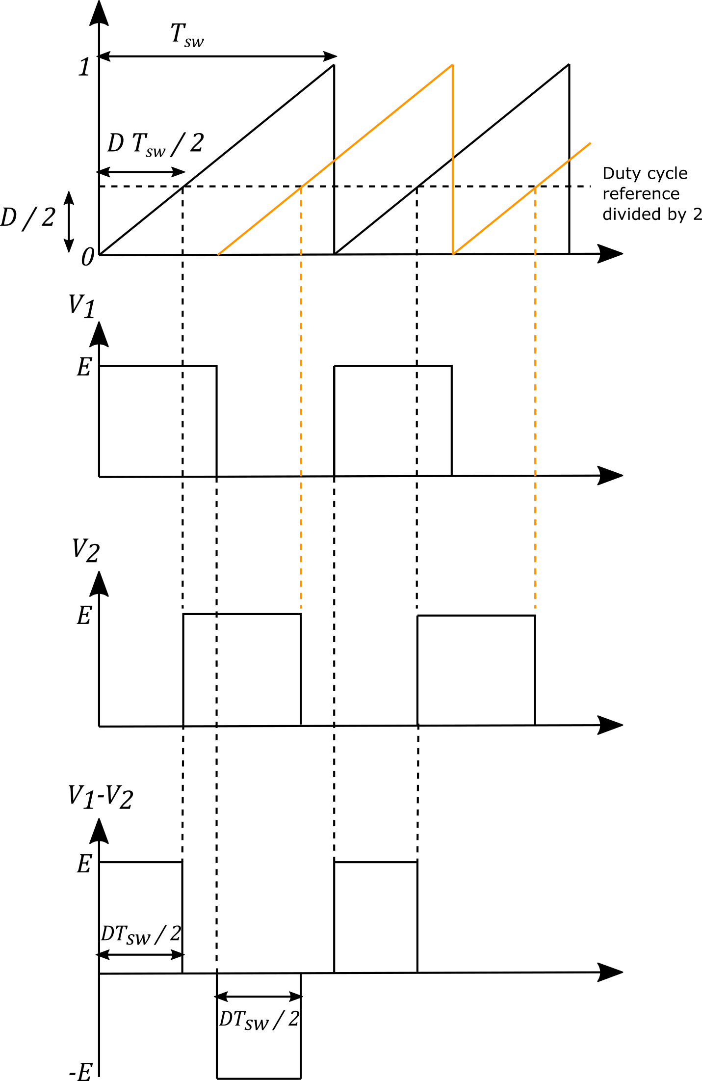
Each switching cell shows its own duty cycle set at 50 %.
- at t=0, the first switching cell is turned on;
- the duty cycle value is first divided by 2;
- this value is compared to a first sawtooh (black) between 0 and 1 at the switching frequency;
- when the sawtooth reaches this value, the second switching cell is turned on;
- at t=T_{sw}/2, the first swithing cell is turned off;
- when the second sawtooth (orange) - delayed of Tsw/2 with the first one - reaches the value of the duty cycle half, the second switching cell is turned off.
Then the differential voltage between the two switching cells shows 4 phases during a switching period:
- E during a time lapse equal to D T_{sw} / 2;
- 0 during time lapse equal to (1-D) T_{sw} / 2;
- -E during a time lapse equal to D T_{sw} / 2;
- 0 during time lapse equal to ((1-D) T_{sw} / 2.
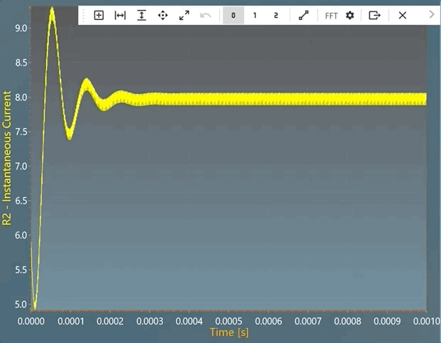
Current loop
This current loop implements an output voltage compensation to simplify the open-loop transfer function and to only keep the integrator behavior of the inductance. Then a simple gain correction can be used.
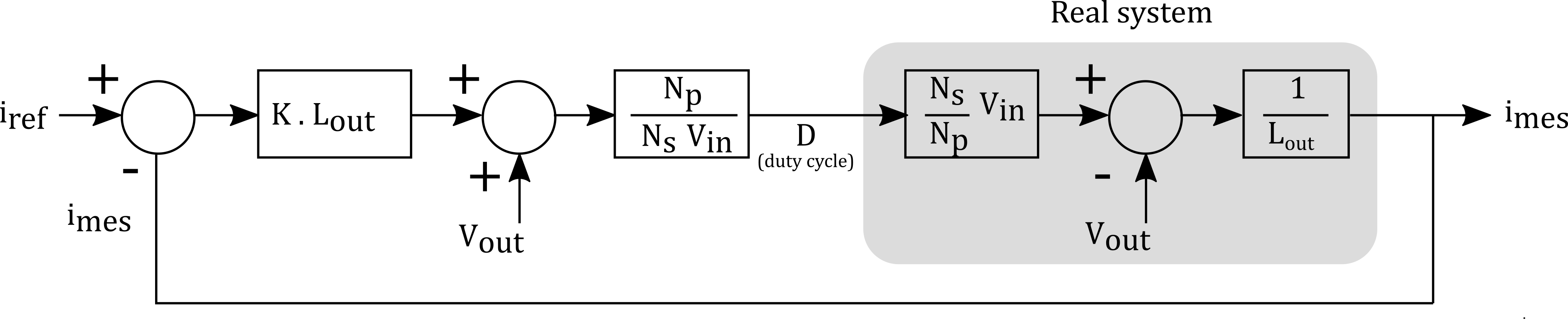
Voltage loop
The voltage loop involves a classic PI regulator.
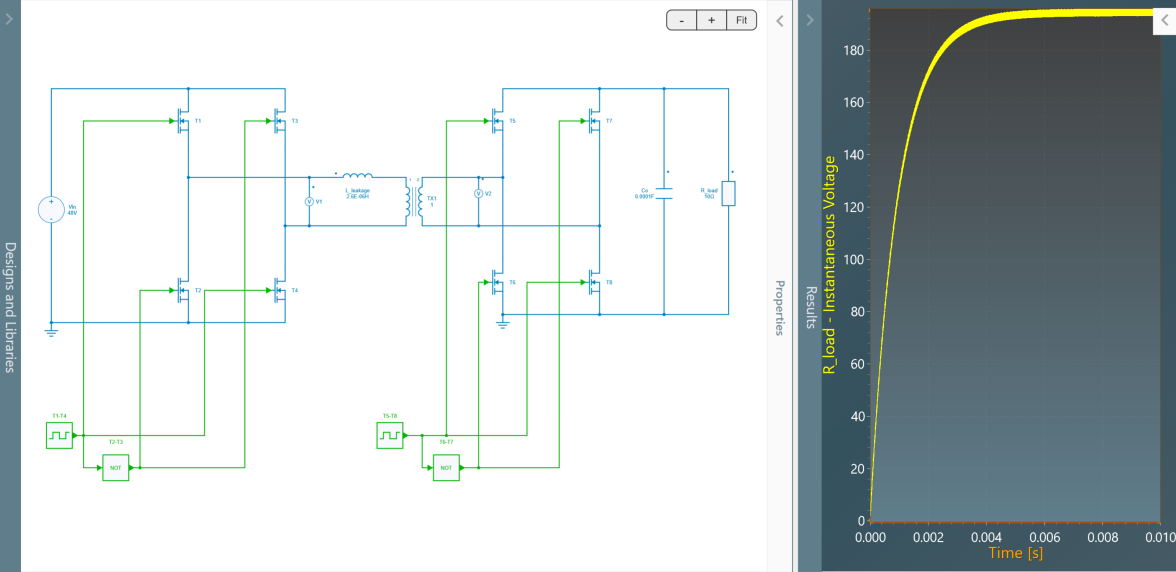
DC/DC Dual Active Bridge Converter Model
This example shows a DC/DC Dual Active Bridge converter with a switching frequency of 100 kHz. We would like to truly thank one of our beta tester, M A Moonem, who took the time to build this great example.
Quality of life
In Beta 4, several bugs are corrected and the general stability of SIMBA is improved.
Roadmap
If you are interested, you can check our roadmap and a public GitHub project is available to share ideas, report bugs, and suggest new features.