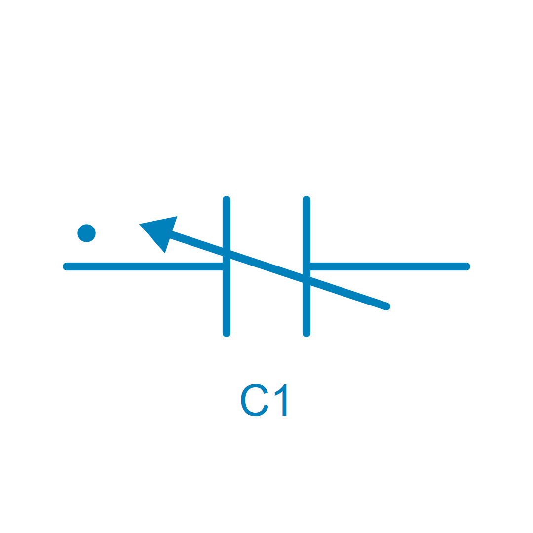
Saturable Capacitor
Description
A voltage-dependent saturable capacitor.
This component represents a nonlinear capacitance using piecewise linear approximation. In this device, capacitance C defined in the property view is an apparent capacitance. The apparent capacitance C is defined as the ratio of charge Q to voltage V across its electrical terminals:
C = \frac {Q}{V}
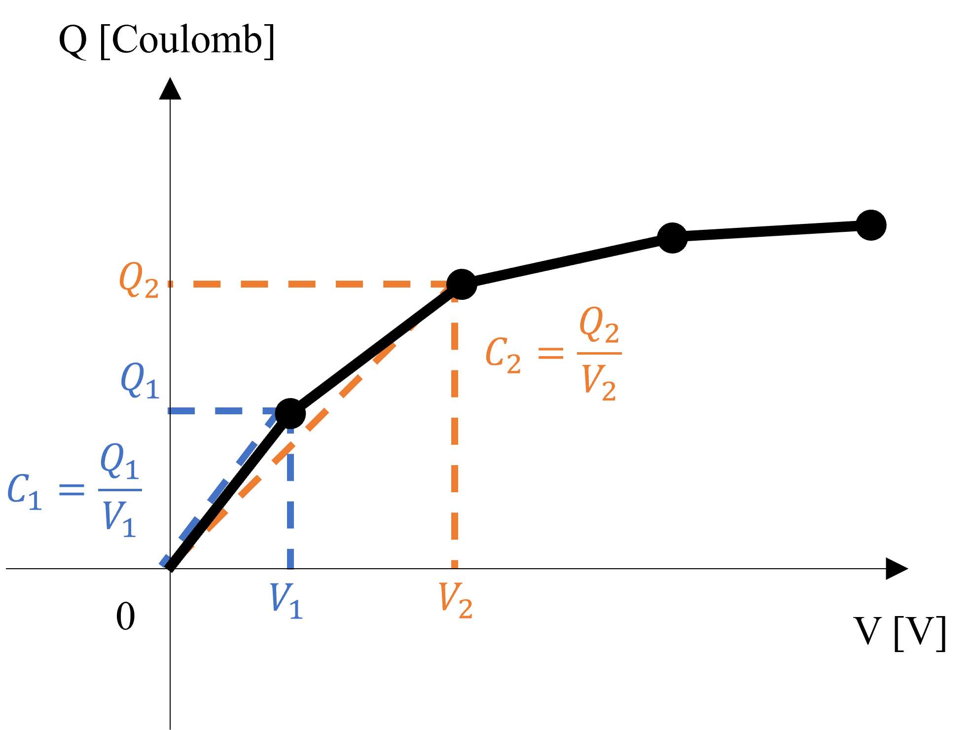
Where charge Q is defined as an absolute value from the origin in the above figure. When the circuit is simulated, SIMBA solver converts this apparent capacitance into a differential capacitance C_{diff}, which is defined as the ratio of the rate of change of charge Q to the rate of change of the voltage V across its electrical terminals. For instance, the differential capacitance between V_1 and V_2 is C_{diff} = \frac {Q_2 - Q_1}{V_2 - V_1}
Saturation is expressed by segmented data points, such as (V1, C1), (V2, C2), (V3, C3), ..., with voltage values (V) ≥ 0. For negative voltage, mirror capacitance values are used. When input voltage falls outside the range of data points, the first or last capacitance value is used. For input voltage between points, the next point is used so that the charge value calculated from the capacitance is linearly interpolated.
SIMBA returns an error if:
- Input data points are not in ascending voltage order.
- Calculated charge Q doesn't monotonically increase with voltage.
- Negative voltage values are included in segmented data points.
Library
Electrical > RLC
Pins
| Name | Description |
|---|---|
| P | Positive Pin (●) |
| N | Negative Pin |
Parameters
| Name | Description |
|---|---|
| ApparentCapacitance | Voltage(V)-Capacitance(F) Matrix |
| Vinit | Initial Capacitor Voltage, in V |