Controlled PWM Generator
Description
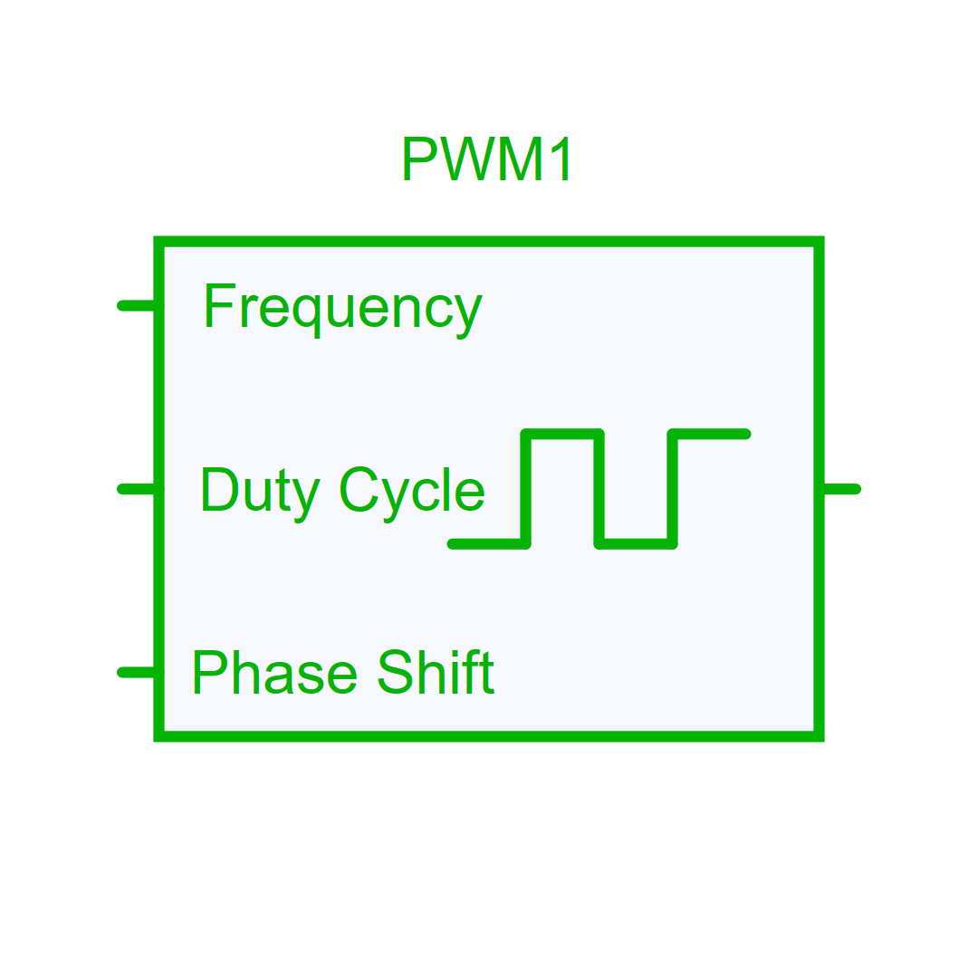
Controlled PWM Generator Signal Source
The PWM output signal is controlled by three input signals that are updated at the beginning of each new period:
- Frequency [Hz]
- Duty-Cycle [0-1]
- Phase Shift [0-360]
The parameters Rise Time and Fall Time can be set. If they are set to 0, the output is purely rectangular.
Library
Control > Sources
Pins
| Name | Description |
|---|---|
| Frequency | Frequency Pin [Hz] |
| DutyCycle | DutyCycle Pin [0-1] |
| PhaseShift | PhaseShift Pin [0-360] |
| Out | PWM Output |
Parameters
| Name | Description |
|---|---|
| RiseTime | Rise Time [s] |
| FallTime | Fall Time [s] |
| SamplingTime | -none or 0: No sampling. The system will be solved in the Newton loop (default). -auto: Inherit the sampling time of its source device. -Sampling Period: defined in seconds. |