Signal Selector
Description
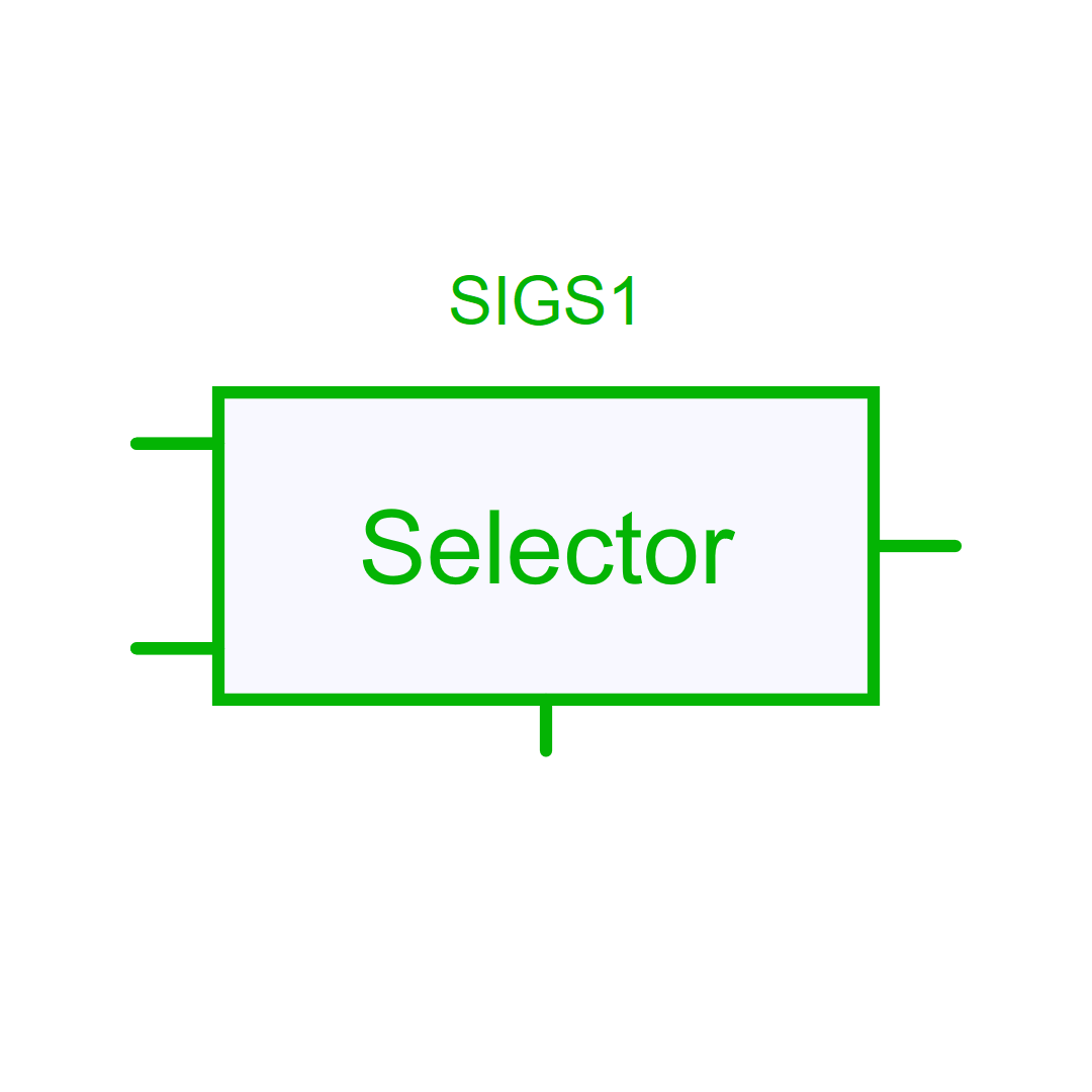
Signal selector
This control block enables the selection of one of the inputs to pass through to the output using a selector pin. The index of the selected input (1 for i1, 2 for i2, etc.) is determined by rounding the selector pin value to the nearest integer. If the selector pin value is below 1, the selected input is i1. If its value exceeds the number of inputs, the selected input is the last one (i3 for 3 pins).
Library
Control > Logic
Pins
| Name | Description |
|---|---|
| i1 | Input 1 |
| i2 | Input 2 |
| Selector | Selector pin |
| Out | Output |
Parameters
| Name | Description |
|---|---|
| NumberOfInputs | Number of Inputs |
| SamplingTime | -none or 0: No sampling. The system will be solved in the Newton loop (default). -auto: Inherit the sampling time of its source device. -Sampling Period: defined in seconds. |