DC/DC Phase Shift Full Bridge
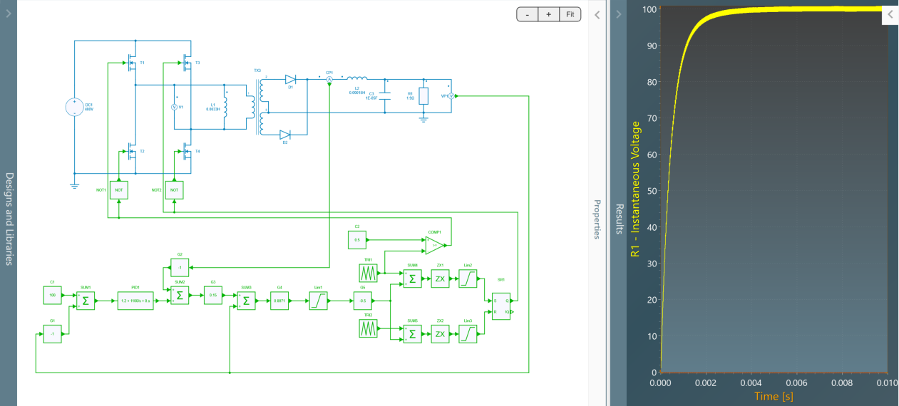
This example, available in SIMBA, shows a Phase-Shift Full Bridge converter with:
- an input voltage of 400 V,
- an output voltage of 100 V,
- a power of 53 kW.
Phase-shift PWM
Each switching cell is driven with a duty cycle of 50%. The control signal of the phase-shifted switching cell is created from the duty cycle reference according to the figure below. The principle is to compare the duty cycle reference with a sawtooth to determine the phase-shift between the two legs.

Each switching cell shows its own duty cycle set at 50 %.
- at t=0, the first switching cell is turned on;
- the duty cycle value is first divided by 2;
- this value is compared to a first sawtooh (black) between 0 and 1 at the switching frequency;
- when the sawtooth reaches this value, the second switching cell is turned on;
- at t=T_{sw}/2, the first swithing cell is turned off;
- when the second sawtooth (orange) - delayed of Tsw/2 with the first one - reaches the value of the duty cycle half, the second switching cell is turned off.
Then the differential voltage between the two switching cells shows 4 phases during a switching period:
- E during a time lapse equal to D T_{sw} / 2;
- 0 during time lapse equal to (1-D) T_{sw} / 2;
- -E during a time lapse equal to D T_{sw} / 2;
- 0 during time lapse equal to ((1-D) T_{sw} / 2.
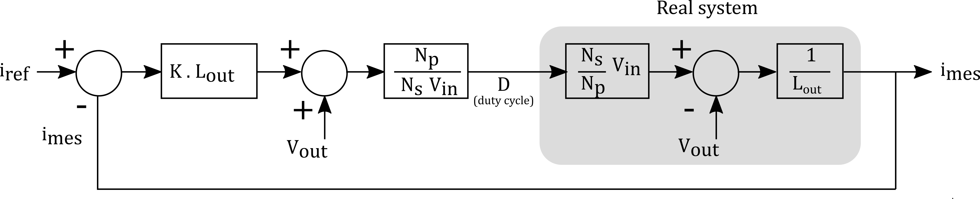
Current loop
This current loop implements an output voltage compensation to simplify the open-loop transfer function and to only keep the integrator behavior of the inductance. Then a simple gain correction can be used.
Voltage loop
The voltage loop involves a classic PI regulator.