Dual Active Bridge
This example, available in SIMBA, shows a Dual Active Bridge converter with:
- an input voltage of 95 V,
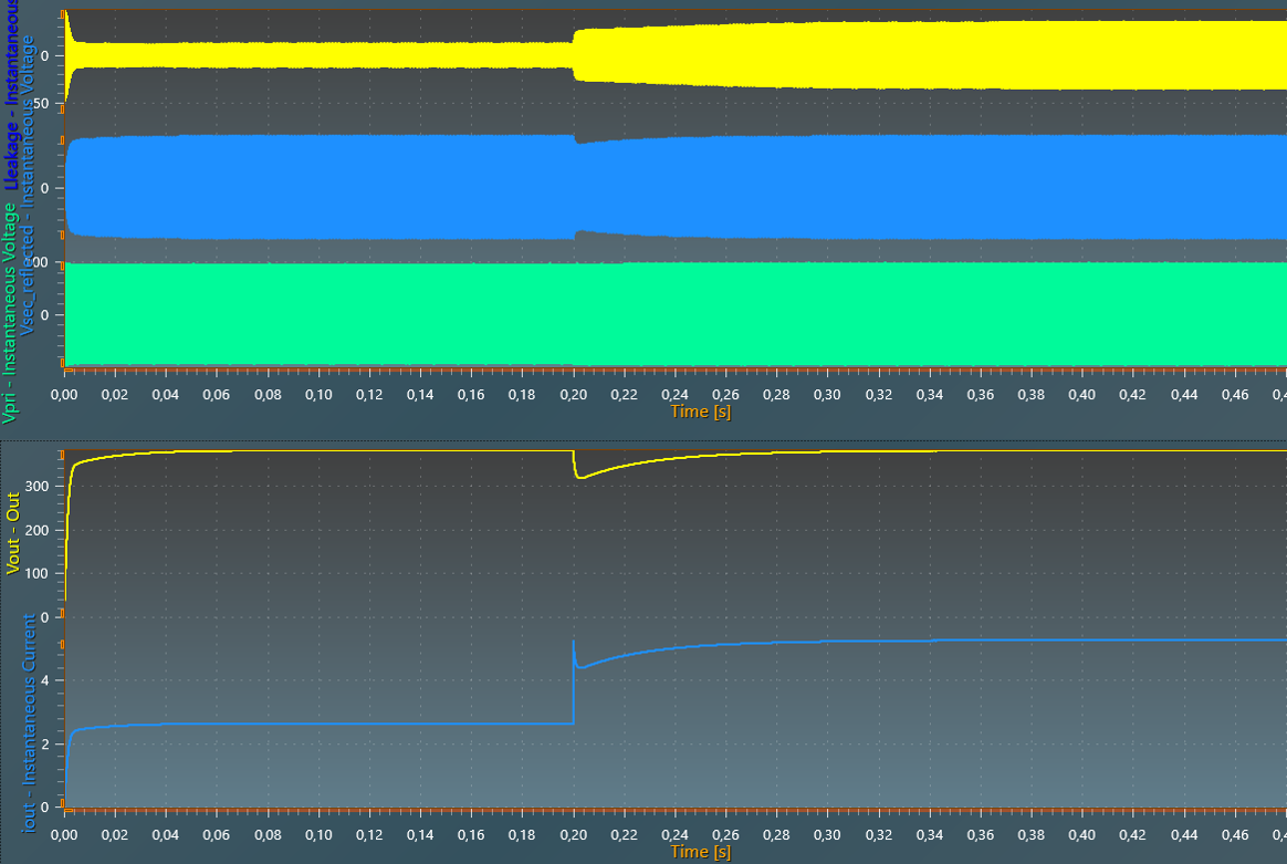
- an output voltage of 380 V,
- a initial output power of 1 kW raised to 2 kW at 200 ms.
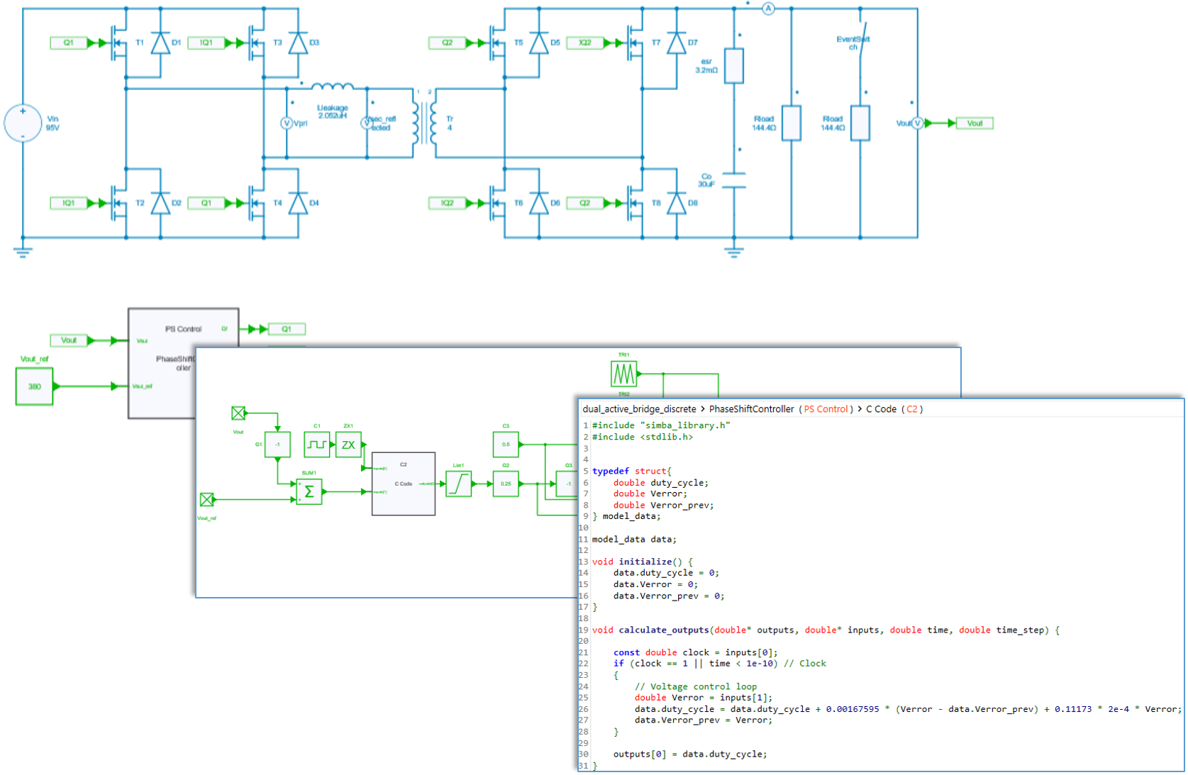
PWM control
Each bridge with a duty cycle of 50%. The phase-shift between the two bridges is set by the discrete controller (PI regulator) in order to regulate the output voltage.
Power semiconductor switches
Mosfets of this example are set with conduction parameters: a first R{on} resistance for the channel conduction mechanism (forward and reverse conduction when the transistor's gate id driven high) and a second R_{on} resistance and a V_f drop voltage for the body diode.
Note : with the command used in this example, mosfets are always used in synchronous rectification mode which means that the controlled conduction mechanism (channel) is the major contributor for conducting the reverse current compared to the body diode conduction.
Transformer ratio
The transformer ratio can be chosen according required values of primary and secondary voltages. Here a secondary voltage of 380V is required and a primary voltage of 95V is considered to be the lowest possible value (worst case), which leads to a transformer ratio of 4.
Inductor design
The expression below gives the maximum power which can be transferred for a phase-shift angle of \pi / 2 [1]:
with m = \frac{V_2}{V_1} the transformer ratio.
A maximum power of 2 kW and a margin of 10 % si considered. At a switching frequency of 250 kHz, with V_1 = 95V and V_2 = 380V, this leads to a maximun inductor value of 2.051 \mu H.
This value is compatible with typical values of leakage inductors of high-frequency transformers with these levels of power, voltages and ratio.
Reference
[1] M. Blanc, Y. Lembeye, J.P. Ferrieux, Dual Active Bridge (DAB) pour la conversion continu-continu, Techniques de l'ingénieur E3975, 2019.